
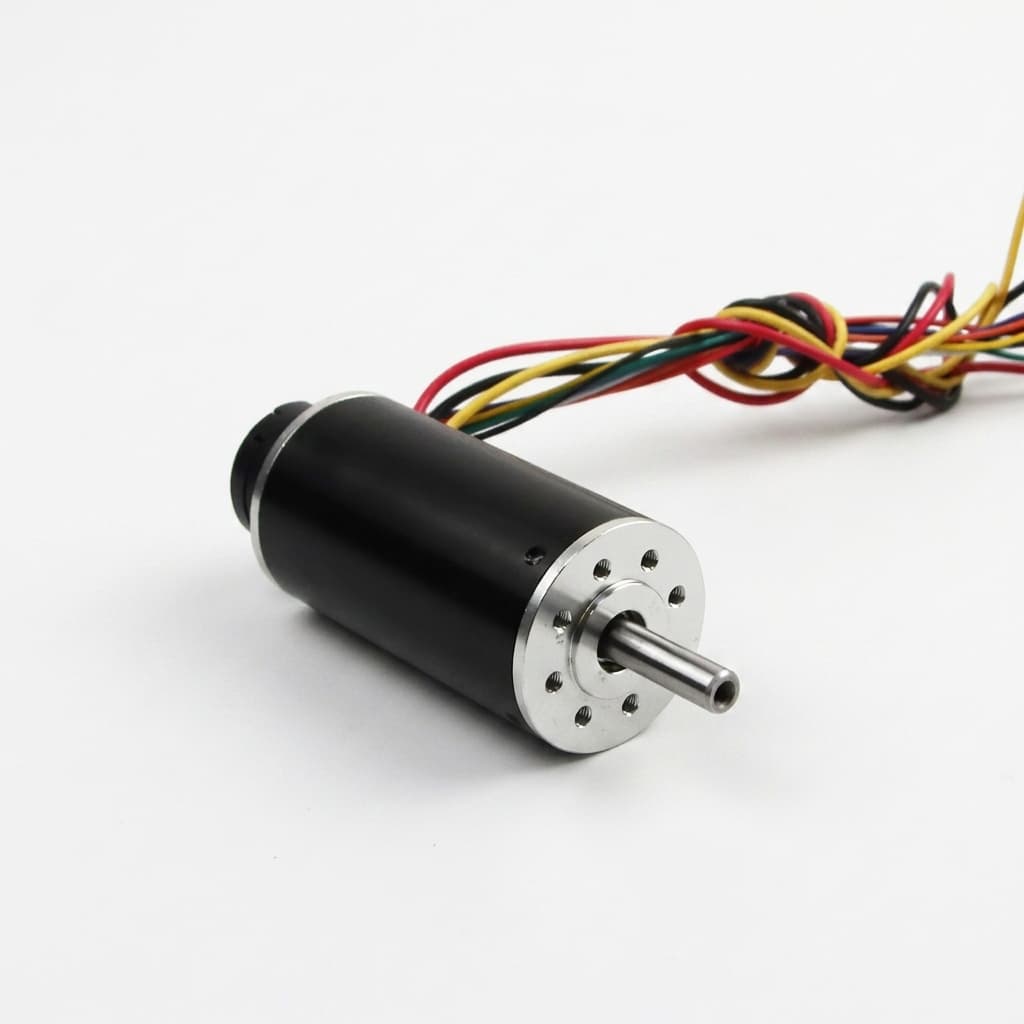
Sensorless vs. Hall Sensor vs. Magnetic Encoder for Micro BLDC Motors: Low-Speed Stability, Starting Torque Under Load, Wiring Overhead, and OEM Sourcing Guide
Micro BLDC feedback selection: compare sensorless, digital Hall and magnetic encoders by torque ripple, low speed and wiring. Use the checklist for OEM RFQs.
When specifying a miniature brushless DC motor—whether for an articulated surgical handpiece, an active camera gimbal, a miniature peristaltic infusion pump, or a multi-axis robotic end-effector—hardware engineering teams face a decisive architecture fork: how will the motor controller detect rotor position?
The three dominant feedback architectures—sensorless (Back-EMF zero-crossing or observer), embedded digital Hall-effect sensors, and miniature magnetic or optical angle encoders—dictate not merely the bill-of-materials (BOM) cost, but also physical package length, wire harness diameter, minimum controllable speed, starting torque reliability, and thermal reliability under continuous duty.
Quick decision framework:
- Consider Sensorless when three phase leads and a compact motor envelope matter most, the load starts freely, and the intended running speed provides adequate back-EMF for the selected controller. Require loaded-start and minimum-speed testing; back-EMF feedback alone cannot identify rotor angle at standstill. Removing sensors does not establish sterilization or temperature suitability.
- Consider Digital Hall Sensors when rotor-sector feedback at standstill helps loaded starting and coarse position feedback meets the application needs. A conventional external drive uses eight conductors: three phase leads plus sensor power, ground, and three Hall outputs. Low-speed smoothness depends on pole pairs, control method, and load inertia.
- Consider an Integrated Magnetic Encoder when fine position feedback, low-speed motion, or controlled holding is required. Confirm the absolute-angle interface or incremental startup strategy, electrical-angle calibration, package drawing, and harness pinout. An encoder enables a suitable control loop; it does not guarantee starting torque, silence, accuracy, or continuous stall capability.
Published and content reviewed: 02 November 2026. Scope: Global OEM engineering and motion control procurement, miniature brushless DC motors (8 mm to 32 mm outer diameter, nominal bus supply up to 48 VDC). This is an architecture comparison for separate motor and drive assemblies, not a qualification of a specific product or medical device. The calculations use the stated idealized assumptions and manufacturer documentation; they are not bench measurements, customer results, or supplier guarantees. Motor-shaft speed must be distinguished from geared output speed. Validate speed-torque curves, loaded starting, thermal limits, and harness details on the actual assembly.
Explore catalog configurations across our Micro BLDC motors, evaluate sensored assemblies via Hall and encoder micro BLDC motors, check compact options through sensorless micro BLDC motors, or submit custom requirements to custom OEM micro BLDC assemblies.
For a configuration review, send your motor-shaft speed range, starting load, and available envelope together with the controller model, if already selected.
1. Architectural Topology: Sensorless vs. Hall vs. Encoder
To evaluate the system-level trade-offs, we must first map the mechanical and electrical topologies of each feedback architecture.
Conceptual layout of sensorless, digital Hall, and magnetic encoder assemblies. Conductor counts and housing dimensions vary by manufacturer frame size and interface protocol.
The physical implementation of each architecture governs electrical performance, mechanical limits, and assembly tolerances. Below, we dissect the core physics behind each technology, identifying where each system excels and where it fails under real-world mechanical and thermal constraints.
2. Core Physics: How Rotor Position Governs Motor Torque
For a sinusoidally modeled permanent-magnet motor, the standard dq torque model is:
Te = (3/2) × p × [λm × iq + (Ld - Lq) × id × iq]
Where:
pis the number of rotor pole pairs,λmis the permanent magnet flux linkage (Wb),iqis the quadrature (torque-producing) current (A),idis the direct (magnetizing or flux-weakening) current (A),LdandLqare direct and quadrature stator inductances (H).
In surface-mounted permanent magnet micro BLDC motors—and especially in slotless or coreless micro motors—the air gap is comparatively wide and magnetic saliency is negligible:
Ld ≈ Lq -> Te = (3/2) × p × λm × iq
Below base speed, with negligible saliency and no flux weakening, id = 0 is a useful operating assumption. The controller needs electrical rotor angle θe = p × θm + θoffset; the offset must be calibrated between the feedback device and windings. For a fixed current-vector magnitude and angle error Δθe, this simplified model gives:
T_actual = T_optimal × cos(Δθe)
At fixed current magnitude, copper loss does not increase solely because the vector rotates. If the controller instead raises current to maintain the same torque, required current scales as 1 / cos(Δθe) and copper loss as 1 / cos(Δθe)^2, within current and voltage limits. The ideal model gives zero forward torque at 90 degrees electrical and reversed torque beyond it. This is an angle-error illustration, not a universal six-step ripple model.
3. Technology 1: Sensorless Commutation (Back-EMF & Observers)
3.1 Operating Principle
In a sensorless drive, rotor feedback comes from electrical measurements rather than a shaft sensor. A six-step drive may sample an undriven phase; an observer-based FOC drive instead estimates back-EMF from current, voltage, and motor parameters. These are distinct approaches, as explained in TI SLVAES1, sections 2.3–2.4.
For a fixed motor, back-EMF magnitude follows |e| = ke × |ωm|; use consistent phase/line and peak/RMS conventions for ke.
In standard six-step trapezoidal commutation, current conducts through two phases at any given instant (e.g., Phase A positive to Phase B return), while the third phase (Phase C) floats. The controller samples the terminal voltage of Phase C and compares it against the virtual motor neutral point to detect the zero-crossing point (ZCP). Once a ZCP occurs, the firmware delays commutation by 30 degrees electrical before executing the next step.
3.2 The Zero-Speed Blind Zone and the Slotless Saliency Trap
At standstill (ωm = 0), motion-induced back-EMF is zero. A controller using only that signal has no rotor-angle observation.
Many back-EMF drives start with an open-loop sequence; exact timing and alternatives depend on the controller:
- Rotor Alignment (Align phase): The inverter excites a predefined phase combination with a current limit, attempting to move the rotor toward a known orientation. Load friction may prevent alignment.
- Open-Loop Ramp (Accelerate phase): The controller steps the commutation frequency open-loop, like a synchronous pulse sequence, until the rotor accelerates to a speed where induced Back-EMF is measurable.
- Closed-Loop Transition: The controller transfers to electrical feedback when signal quality and observer convergence meet its criteria. There is no universal voltage or speed threshold across micro motors and drives.
[!WARNING] Low-saliency boundary: High-frequency injection (HFI) needs a measurable angle-dependent electrical response. Slotless and coreless designs often offer little geometric saliency, so do not assume an HFI feature will provide reliable standstill angle detection. Require controller-specific evidence on the actual motor, temperature range, and load; the construction label alone cannot prove or rule out every injection method.
3.3 Where Sensorless Fails in Production
- Startup Hesitation & Reverse Kick: During the alignment phase, if the rotor rests near the 180-degree unstable equilibrium point, it can snap backwards by up to half a pole pitch before moving forward. In surgical articulators, valve dosers, or robotic finger joints, this uncontrolled reverse kick is unacceptable.
- Stalling Under Friction or Back-Pressure: If a peristaltic pump has high roller compression or grease viscosity at cold start, the open-loop ramp current may be insufficient to accelerate the rotor. The motor loses synchronism, stalls, and triggers an overcurrent fault.
- Minimum Operating Speed Limit: It depends on winding back-EMF constant, sensing noise, current sampling, load, and controller implementation. As an illustrative calculation only, a winding with
ke = 0.5 mV/RPMproduces 100 mV at 200 RPM under the same voltage convention. That arithmetic does not establish detectability. Request a demonstrated minimum motor-shaft speed under your load and supply conditions rather than specifying a generic RPM cutoff.
4. Technology 2: Digital Hall-Effect Sensors
4.1 Operating Principle
Digital Hall-effect sensors are solid-state magnetic switches integrated onto a small flexible or rigid circuit board positioned inside the motor's rear endbell.
Three sensors (labeled Hall A, Hall B, Hall C) are mounted with an electrical spacing of either 120 degrees or 60 degrees. As the rotor's permanent magnet poles sweep across the sensors, each Hall output transitions between digital high (VCC) and digital low (GND).
For a conventional 120-degree arrangement, six valid three-bit states divide an electrical revolution into six sectors. The state sequence depends on wiring and direction; 60-degree arrangements need the appropriate truth table. TI SLVAEG3, pages 2–3 describes Hall-sector commutation and electrical versus mechanical placement.
4.2 Mechanical & Electrical Realities
- Sector Feedback at Standstill: Valid Hall states let a correctly mapped controller choose a starting commutation sector without back-EMF. Available torque and startup motion still depend on current limit, Hall-phase alignment, rotor position within the sector, and load friction; test all starting positions.
- Six-Step Commutation Torque Ripple: In an ideal sinusoidal torque-angle example with fixed current and electrical-angle error varying by ±30 degrees, the torque reduction from the best angle is:
Illustrative torque reduction = 1 - cos(30°) = 13.4%
This is not a universal measured ripple percentage: trapezoidal back-EMF, current waveforms, commutation overlap, cogging, and the ripple definition all matter. Agree a peak-to-peak or RMS metric, speed, load, current limit, and measurement bandwidth when comparing drives. Hall feedback can also support interpolated sinusoidal control rather than six-step control alone.
4.3 Low-Speed Velocity Jitter and the Minimum Speed Boundary
In closed-loop velocity control, the microcontroller calculates speed by timing the intervals between Hall edge transitions.
For a motor with p pole pairs:
- Number of Hall transitions per mechanical revolution =
6 × p. - For a common 2-pole motor (
p = 1), there are only 6 pulses per mechanical revolution (60 degrees mechanical resolution). - At 60 RPM (1 rev/second), an edge transition arrives only once every 166.7 ms.
A velocity control loop running at 1 kHz executes about 167 iterations between edges in that example. An observer may estimate motion between edges, but the sparse measurements limit the directly observed response to load disturbances.
[!TIP]
Reproducible screening calculation: At motor speed n in RPM, the Hall edge interval is Δt = 10 / (p × n) seconds. If a project requires a new measured sector at least every 20 ms, then n ≥ 500 / p RPM: 500 RPM for one pole pair or 250 RPM for two. The 20 ms requirement is an illustrative design choice, not a manufacturer limit or proof of stable control. A geared output at 10 RPM with 100:1 reduction turns the motor at approximately 1,000 RPM; screen feedback at the motor shaft and assess gearbox backlash separately.
5. Technology 3: Miniature Magnetic and Optical Encoders
5.1 Operating Principle
Fine position feedback from an encoder is useful for precision positioning, slow motion, and controlled holding. FOC itself does not require an encoder: sensorless observers and Hall interpolation are alternatives when their operating limits fit. TI SLAAE96 describes one sensorless FOC implementation.
Magnetic angle encoders avoid an exposed optical code path, but sensor technology should be selected against packaging, contamination, accuracy, and magnetic-field conditions rather than a blanket preference.
An on-axis magnetic encoder comprises two components:
- A small, diametrically magnetized permanent magnet disk bonded directly to the extended rear shaft of the rotor.
- A specialized CMOS Hall-array or Anisotropic Magnetoresistive (AMR) / Giant Magnetoresistive (GMR) sensor IC mounted on a PCB stationary over the magnet.
The IC converts the rotating magnetic field into angle data. Hall-array, magnetoresistive, and other sensing implementations differ; CORDIC processing and a particular interface are not universal. As a concrete example, the MPS MA730 lists 14-bit absolute angle readout over SPI and a programmable ABZ output with up to 1,024 pulses per turn per channel. An integrated motor may use a different device and interface.
   [ Extended Motor Shaft ] ---> [ Diametric Target Magnet ]
                                          |
                                (Gap per sensor drawing)
                                          |
                                 [ CMOS Sensor Array ]
                                 [ Angle Processing ]
                                          |
                        +-----------------+-----------------+
                        |                                   |
                [ Incremental ABZ ]                 [ Absolute Serial ]
               (PPR per selected IC)             (Protocol per selected IC)
5.2 Enabling Pure Field-Oriented Control (FOC)
Resolution is not accuracy. A 14-bit absolute word divides a turn into 16,384 codes: 360° / 16,384 ≈ 0.022° per code. Sensor nonlinearity, noise, eccentricity, magnet tilt, temperature, and latency can produce larger angle errors. Specify absolute-angle bits separately from ABZ pulses per revolution and the controller's quadrature decoding factor.
With calibrated electrical angle and adequate sensor bandwidth, the drive can use Park and Clarke transformations for closed-loop current control. Procurement acceptance should establish:
- Torque ripple: Measure it over the required speed and load range; an encoder alone does not remove cogging, current ripple, or gearbox disturbances.
- Acoustic noise: Record the measurement distance, background level, PWM settings, and mounting. FOC can reduce commutation excitation but cannot promise silence.
- Zero-speed holding: Specify permitted continuous holding current, duration, temperature rise, and cooling. Continuous holding torque may be much lower than peak stall torque. Incremental-only ABZ needs a reference or other commutation feedback at startup; absolute shaft angle still needs electrical-offset calibration and may not identify a multi-turn joint position.
5.3 Engineering Trade-offs & Failure Modes
While encoders provide peak motion fidelity, they introduce serious mechanical, electrical, and thermal constraints:
- Added Package Length: Use the supplier's assembly drawing for the magnet, PCB, bearing support, shielding, and cable exit. As geometry arithmetic only, a 6 mm extension on a 20 mm body adds 30% to body length; it is not a standard encoder allowance.
- Thermal Derating: Winding insulation class is not a rating for the complete motor, sensor, adhesive, or lubricant. The MA730 example specifies an operating range of -40°C to +125°C; other ICs differ. Check operating conditions separately from absolute maximum ratings and measure sensor-board temperature during the required duty cycle. Winding temperature cannot simply be substituted for sensor temperature.
- Magnetic Cross-Talk: In compact micro BLDC assemblies, high currents switching in the stator windings generate stray alternating magnetic fields. If the target magnet is poorly shielded, this field couples into the sensor array, causing periodic angle distortion and velocity ripple.
6. Comprehensive Engineering Comparison Matrix
This compares architectures, not guaranteed catalogue performance. Speed, ripple, length, and cost need a matched motor-controller quotation and sample acceptance test.
| Engineering Parameter | Sensorless (Back-EMF / Observer) | Embedded Digital Hall Sensors | High-Resolution Magnetic Encoder |
|---|---|---|---|
| Position Feedback | Back-EMF crossing or model-based estimate while running | Six sectors per electrical revolution | Fine angle; absolute word and ABZ pulse count are separate specifications |
| 0-RPM Starting Under Friction | Needs a validated startup strategy; back-EMF alone gives no standstill angle | Sector known with valid Hall mapping; verify current and loaded starts | Absolute angle plus calibrated electrical offset, or an incremental startup reference |
| Minimum Stable Motor Speed | Controller, winding, noise, and load dependent | Edge interval 10 / (p × n) seconds; stability also depends on the loop | Finer feedback helps; verify friction, bandwidth, and speed ripple at the required speed |
| Commutation Torque Ripple | Depends on six-step or observer FOC implementation | Six-step or interpolated control; no universal ripple percentage | FOC may reduce ripple; verify motor and drive together |
| Acoustic Noise Profile | Check startup transients and operating noise | Check commutation and PWM excitation | Check PWM, bearings, mounting, and control tuning; silence is not guaranteed |
| Motor Wire Harness Count | 3 phase conductors | 8 with three discrete Hall outputs | 8 single-ended ABZ; 9 full-duplex SPI or differential clock/data; 11 differential ABZ, before extras |
| Axial Length Overhead | No feedback PCB; use motor drawing | PCB may fit inside the existing endbell | Magnet, sensor, support, and cable exit per assembly drawing |
| Thermal Constraint | Windings, magnets, bearings, adhesives, and external drive | Motor limits plus the selected Hall IC operating rating | Motor limits plus sensor-board temperature and the selected encoder operating rating |
| Autoclave / Sterilization Readiness | Complete motor still requires cycle validation | Sealing, ICs, wiring, and adhesives require validation | Sealing, alignment, magnet attachment, and ICs require validation |
| Cost to Compare in RFQ | Motor plus startup tuning and drive | Motor plus Hall assembly, harness, and EOL alignment checks | Motor plus sensor, calibration, interface electronics, and harness; no universal BOM multiplier |
| Candidate OEM Applications | Fans, drills, centrifugal pumps | Pumps, tools, blowers | Grippers, gimbals, positioning stages; validate the actual duty |
7. The Wire Harness Penalty: Routing in Miniature Mechatronics
Cable routing can consume a meaningful share of a miniature joint's torque budget. Bend stiffness creates restoring torque, while rotor inertia governs acceleration torque; assess each against the application torque budget rather than comparing stiffness directly with inertia.
Sensorless:       3 = U + V + W
Digital Hall:     8 = 3 phase + VCC + GND + Hall A + Hall B + Hall C
Single-ended ABZ: 8 = 3 phase + VCC + GND + A + B + Z
Differential ABZ: 11 = 3 phase + VCC + GND + A+/A- + B+/B- + Z+/Z-
7.1 Cable Stiffness and Parasitic Joint Torque
In robotic finger joints or camera gimbals, a cable bundle can transmit vibration, consume holding torque, and fatigue during repeated flexing. Measure restoring torque across the actual joint travel and temperature range. Wire gauge, stranding, insulation, twist, shielding, jacket, and routing determine outer diameter and dynamic bend radius; conductor count alone cannot supply either value.
The counts below assume a separate drive and include three phase leads. They exclude shields, drains, temperature sensors, brakes, and additional Hall outputs. A shield may need its own slip-ring path. For every row, obtain OD and dynamic bend radius from the selected cable supplier, and qualify any slip ring for phase current, signal integrity, and life.
| Cable Configuration | Conductors | Count Derivation | Routing / Procurement Check |
|---|---|---|---|
| Sensorless | 3 | 3 phase | Size phase conductors for current and flex life |
| Digital Hall | 8 | 3 phase + 2 power + 3 Hall | Confirm logic levels and return paths |
| Single-Ended ABZ | 8 | 3 phase + 2 power + A/B/Z | State pulse rate and receiver thresholds |
| Differential ABZ | 11 | 3 phase + 2 power + 6 signal | Three differential pairs; specify receiver termination |
| Read-Only SPI | 8 | 3 phase + 2 power + clock/CS/data | Only when the device supports a read-only connection |
| Full-Duplex SPI | 9 | 3 phase + 2 power + SCLK/CS/MOSI/MISO | Confirm clock rate, return path, and cable loading |
| Differential SSI / BiSS-C | 9 | 3 phase + 2 power + clock pair + data pair | Assumes this physical interface; verify actual pinout |
7.2 EMI Susceptibility
PWM edges on phase leads can couple into adjacent sensor lines. Separate phase and feedback routing where practical; twist differential signals with their complements and follow the receiver's termination requirements. For single-ended signals, design the return path and shielding for the selected interface. Validate angle error or packet integrity under maximum current and switching conditions, and require the drive to handle invalid feedback safely.
Before freezing connector size, request a pinout and harness review with cable travel, bend radius, interface rate, and phase-current requirements.
8. Application Selection Guide: Matching Architecture to Product Requirements
These are illustrative requirement profiles, not tested devices or customer case studies. Compare motor-shaft and output-shaft requirements before applying them.
Case 1: Miniature Peristaltic & Syringe Infusion Pumps
- Illustrative Requirements: 10 to 100 output RPM, high starting load from tubing pinch or pressure, a specified reverse-displacement limit, and quiet operation.
- Selection to Evaluate: Magnetic Encoder + FOC Drive for direct-drive low-speed motion. With a gearbox, the motor may run fast enough for Hall feedback. Test startup displacement and flow pulsation against pressure, tubing, gearing, and temperature; smooth shaft rotation alone does not validate dosing accuracy or medical suitability.
Case 2: Handheld High-Speed Surgical Drills & Dental Handpieces
- Illustrative Requirements: 40,000 to 100,000 motor RPM, slim pen grip, a specified sterilization process and cycle life, and a compact cable.
- Selection to Evaluate: Sensorless BLDC can reduce internal electronics and phase-lead count. Confirm electrical frequency
fe = p × n / 60, drive sampling/PWM capability, overspeed limits, startup load, and thermal behavior. Sensor removal does not qualify bearings, adhesives, insulation, or seals for sterilization; request complete-assembly cycle evidence.
Case 3: Compact Drone Micro Propulsion & Centrifugal Air Blowers
- Illustrative Requirements: Continuous high-speed unidirectional rotation, aerodynamic load, and a strict weight limit.
- Selection to Evaluate: Sensorless BLDC for an impeller that starts freely. Aerodynamic torque may be small at rest, but bearings, seals, rubbing, or debris still create breakaway load. Test restart, windmilling, low bus voltage, and obstruction recovery rather than assuming a frictionless start.
Case 4: Surgical Robotic Articulators & Multi-Axis Robotic Grippers
- Illustrative Requirements: Fine bidirectional positioning, holding at zero speed, dynamic reversal under load, and a compact joint envelope.
- Selection to Evaluate: Absolute Magnetic Encoder with a compatible drive. Check absolute accuracy, latency, electrical-offset calibration, and load-side backlash. A single-turn motor encoder does not establish multi-turn joint position after power loss; homing, retained turn counting, or a load-side sensor may still be needed. Verify holding current and temperature rise at the required payload.
9. OEM Commutation & Feedback Specification Checklist
When requesting quotes (RFQ) or drafting specifications for custom micro BLDC motors, use this checklist to remove ambiguities between your engineering team and the factory:
- Commutation Scheme Defined: Specify six-step trapezoidal or sinusoidal Field-Oriented Control (FOC), controller model, and motor pole-pair count.
- Sensor Type & Model: State sensorless, digital Hall (IC part number and output type), or encoder (IC, absolute resolution/accuracy, ABZ PPR, and decoding factor). For example, 12-bit absolute angle means 4,096 codes per turn, not necessarily 4,096 ABZ pulses.
- Electrical Placement Angle: For Hall sensors, define 120-degree or 60-degree electrical placement and the corresponding truth table.
- Hall Placement Angular Accuracy: Agree permissible electrical phase error, phase sequence, datum, and measurement method; require a phase-to-Hall alignment record.
- Encoder Output Protocol: Specify incremental ABZ or absolute serial, physical interface, maximum signal/clock rate, latency, electrical-offset calibration, and startup reference strategy.
- Supply Voltage Range: Define sensor VCC, logic levels, startup current, and pull-ups from the selected IC and controller ratings; include cable voltage drop.
- Harness Shielding & Twisting: Define signal pairs, returns, shield termination, cable length, and error criteria with maximum phase current and PWM switching active.
- Target Magnet Attachment & Runout: Set magnet grade, retention, gap, tilt, runout, and calibration limits from the encoder's magnetic-field requirements and assembly drawing.
- Operating Temperature Envelope: Specify ambient range, duty cycle, continuous holding current, permitted winding and sensor-board temperatures, cooling, and validation method.
- Factory End-of-Line (EOL) Testing: Agree production coverage and records for Hall transition timing or encoder angle error, calibration, and feedback-loss response, as applicable.
- Loaded-Start Acceptance: Define starting load, supply extremes, temperature, rotor starting positions, allowed reverse displacement, startup time, and repeat count. Agree numerical pass/fail limits before ordering samples.
- Low-Speed Acceptance: State motor/output speeds and gear ratio, permitted speed ripple, load disturbances, measurement bandwidth, and settling time. Attach traces from the proposed motor-controller combination.
10. Frequently Asked Questions (FAQ)
Can I run Field-Oriented Control using only digital Hall sensors?
Yes. A suitable controller can interpolate angle between Hall edges with a PLL or observer. Sparse updates make low-speed disturbance rejection harder; there is no universal RPM threshold. Use the pole-pair/edge-interval calculation in section 4 and verify loaded performance. Fine encoder feedback is worth evaluating when interpolation cannot meet the motion specification.
Why do some sensorless micro motors vibrate and refuse to start under load?
At standstill, motion-induced back-EMF is zero. During alignment and an open-loop ramp, friction, inertia, or opposing pressure may prevent the rotor from following the commanded field. It can oscillate or stall until protection acts. Review current limits, startup timing, load, and the controller's supported initial-position method; do not increase current without checking motor and drive limits.
What is the advantage of analog Hall sensors over digital Hall sensors?
A suitably designed analog sin/cos feedback assembly can provide angle information between digital Hall edges, including at standstill. A generic analog Hall sensor does not automatically supply calibrated quadrature signals. The controller must correct offset, gain, phase, and temperature errors; verify whether the output represents electrical or mechanical angle. Such an assembly performs an encoder-like function and still needs packaging and calibration.
How much axial length does an integrated magnetic encoder add to a micro BLDC motor?
There is no universal allowance. Request a dimensioned assembly drawing including the target magnet, shaft extension, PCB, cable exit, and installation clearance. An endbell-integrated or off-axis layout can differ substantially from a rear-mounted module. Compare the complete envelope rather than sensor IC thickness alone.
Can encoder-equipped micro BLDC motors withstand steam autoclaving?
Do not infer steam resistance from an encoder's dry operating-temperature rating. Require complete-assembly evidence for the specified steam process, cycle count, seals, adhesives, magnet attachment, bearings, and post-cycle angle accuracy. A sensorless motor also requires this validation. Without that evidence, neither configuration is approved for the process.
What is the maximum cable length for an encoder on a micro BLDC motor?
It depends on signal rate, driver/receiver ratings, cable loading, termination, grounding, and PWM exposure. There is no universal SPI, ABZ, SSI, or BiSS-C cable-length guarantee. Differential signaling may improve noise tolerance, but these protocol names are not interchangeable electrical standards. Obtain an interface-specific length/rate limit and verify errors with the intended cable and drive operating.
Why do Hall sensors fail in high-temperature micro BLDC motors?
Heat can change magnetic switching thresholds or exceed IC, PCB, connector, or adhesive operating limits. Select the actual Hall part for the measured local temperature and magnetic field, and verify transition timing over temperature. Motor insulation classes do not classify Hall ICs; automotive qualification alone does not establish assembly temperature capability.
How do I eliminate the reverse snap on sensorless motor startup?
Specify a numerical reverse-displacement limit and test starts across rotor positions, temperature, supply, and load. Validated Hall or absolute-angle feedback is a practical starting point. Some controllers offer inductive initial-position detection, but performance depends on the motor's measurable response; do not assume it works on a low-saliency motor. Feedback choice alone cannot certify zero reverse motion.
11. Sources & Authoritative Engineering References
Sources checked on 02 November 2026. These primary documents support the architecture and the identified component example; they do not validate a specific Micro BLDC assembly or establish universal speed, cost, acoustic, or sterilization limits.
- Texas Instruments SLVAES1, Brushless-DC Motor Driver Considerations and Selection Guide, revision A. Sections 2.3–2.4 distinguish control methods and feedback architectures.
- Texas Instruments SLVAEG3, Brushless DC Motor Commutation Using Hall-Effect Sensors, revision B. Pages 2–4 cover Hall-sector switching, placement, and sensor selection.
- Texas Instruments SLAAE96, BLDC and PMSM Control Using Sensorless FOC Algorithm Based on MSPM0 MCUs, revision A. An example of FOC implemented without a shaft encoder, not a qualification for every micro motor.
- Monolithic Power Systems MA730, 14-Bit, Digital, Contactless Angle Sensor with ABZ Incremental & PWM Outputs. Product specifications identify absolute resolution, SPI readout, ABZ pulse settings, and operating temperature for this component only.
12. Request Engineering Review & Custom Motor Sourcing
Sourcing the optimal micro BLDC feedback configuration requires balancing motor envelope, harness routing, low-speed control fidelity, and unit manufacturing cost:
- Explore catalog configurations across our Hall and encoder micro BLDC motors.
- Review high-speed, compact designs with sensorless micro BLDC motors.
- Evaluate all-in-one actuator packages with integrated FOC micro BLDC motors.
- For custom shaft lengths, custom flex-harness terminations, high-temperature Hall installations, or calibrated magnetic encoder integration, contact our engineering team with your speed, torque, supply voltage, and space envelope specifications.
Author

Categories
More Posts
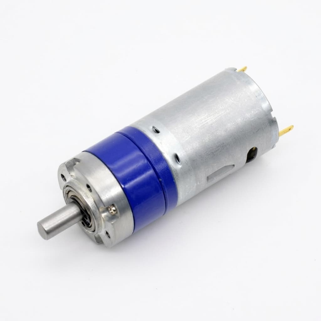
Micro BLDC Gearhead Selection: Miniature Planetary vs. Spur vs. Strain Wave Reducers — Speed Limits, Backlash, Efficiency, and OEM Sourcing
Micro BLDC gearhead selection: compare planetary, spur and strain wave reducers by speed, backlash and efficiency. Use the checklist to prepare your OEM RFQ.

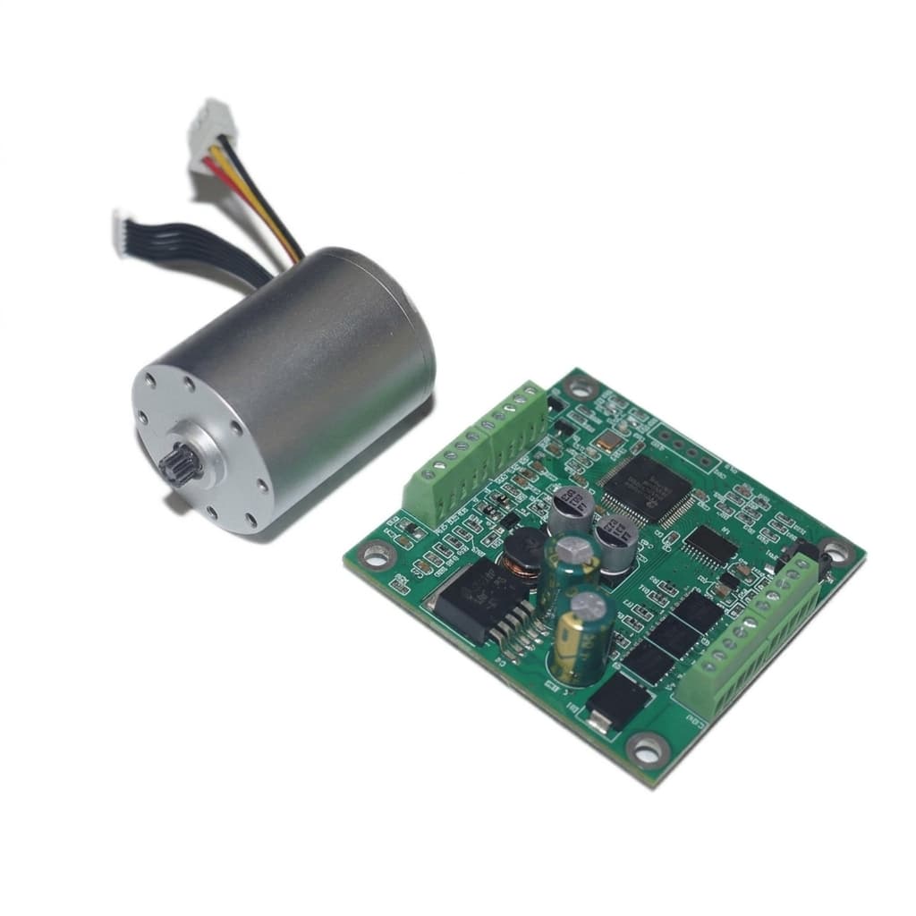
Integrated FOC Driver vs. External Driver for Micro BLDC Motors: Engineering Trade-offs, Thermal Limits, and OEM Procurement Guide
Compare integrated FOC vs external drivers for micro BLDC motors, including thermal limits, wiring, EMC, and lifetime cost. Prepare your OEM qualification RFQ.
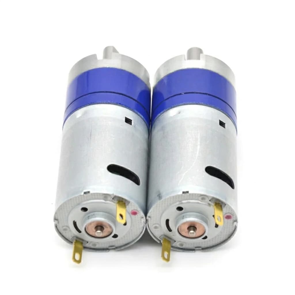
Micro BLDC Motor Sizing Guide for Compact Robotics
A practical engineering guide on calculating RMS torque, gear ratio efficiency, and thermal limits when specifying micro BLDC gear motors for robotic joints and grippers.