
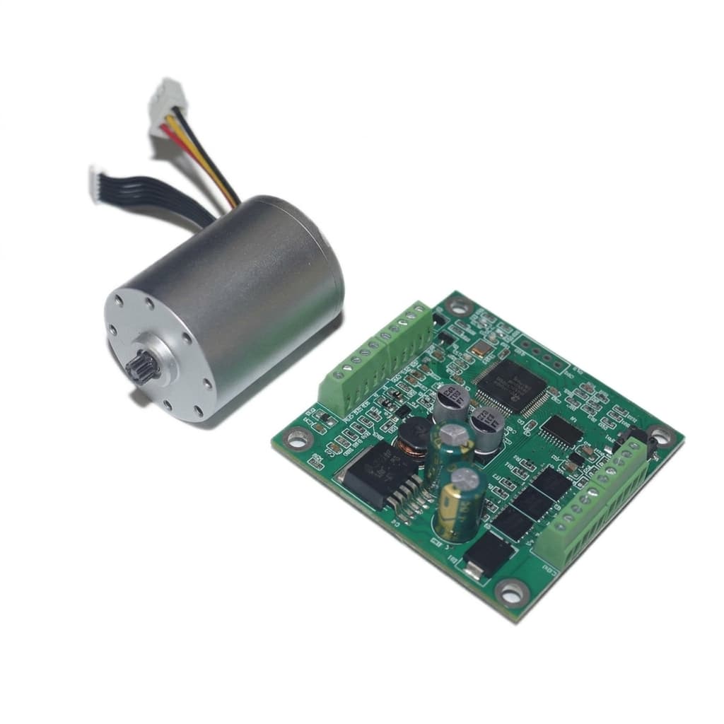
Integrated FOC Driver vs. External Driver for Micro BLDC Motors: Engineering Trade-offs, Thermal Limits, and OEM Procurement Guide
Compare integrated FOC vs external drivers for micro BLDC motors, including thermal limits, wiring, EMC, and lifetime cost. Prepare your OEM qualification RFQ.
When architecting high-density mechatronic assemblies—such as collaborative robotic joints, multi-axis surgical articulators, compact peristaltic infusion pumps, and pan-tilt gimbal systems—engineering teams face a fundamental hardware design fork: should you specify a micro BLDC motor with an integrated Field-Oriented Control (FOC) driver, or pair a discrete motor with an external electronic speed controller (ESC)?
Quick decision: Favor an integrated FOC motor when joint wiring and packaging dominate, provided the complete assembly meets your thermal and control requirements. Favor an external driver when separate cooling, service access, or control ownership matters more. Either architecture can use FOC; driver location and commutation method are separate decisions.
Placing the inverter and control electronics inside the motor housing couples their cooling requirements to the stator. It can also change the field-replacement boundary: a sealed assembly may require replacing both motor and electronics after one component fails.
Published and technically reviewed: 27 October 2026. Scope: global OEM engineering and procurement, compact low-voltage BLDC assemblies. This is a documentation-based engineering comparison, not a measured product test or supplier quotation. Numerical examples below are explicit assumptions. Device ratings, market-specific compliance, pricing, MOQ, and lead time require project confirmation.
Use the comparison, qualification checklist, and RFQ template below to shortlist an architecture. For a project review, send your load profile and packaging limits.
1. Architectural Overview: Decentralized Smart Motor vs. Centralized Drive
To evaluate the system-level implications, we must first map the physical and electrical topology of both approaches.
Conceptual topology, not a product drawing or performance test. Read the conductor-count assumptions below.
Architecture A: Decentralized Integrated FOC Actuator
The commutation controller and three-phase inverter are mounted in or on the motor housing. Positioning applications may add an encoder; speed-controlled applications may use sensorless FOC. FOC does not itself imply a position loop, CAN interface, or factory encoder calibration.
For a motor that explicitly supports CAN or an RS-485-based protocol, an illustrative harness has:
DC Power (+V)Power Ground (GND)Differential Bus High (CAN-H / RS485-A)Differential Bus Low (CAN-L / RS485-B)
Example wire count: 4 core conductors, before shield/drain, protective bonding, bus reference, enable, brake, or safety wiring. Check the actual pinout. SPI and BiSS-C use different signal arrangements and are not substitutes for this four-conductor example.
Architecture B: Centralized Drive with Discrete Micro Motor
In this topology, the motor contains the windings, rotor, bearings, and optional feedback sensors. Three phase leads (U, V, W) and any feedback lines run back to a separate drive board or enclosure. An external ESC can implement six-step commutation or FOC; compare control capability separately from packaging.
Example wire counts, before shields and auxiliary wiring:
- Sensorless: 3 phase leads carrying PWM voltage.
- Hall feedback: 3 phase + 5 Hall leads = 8 conductors, including Hall power and ground.
- Differential incremental encoder: 3 phase + 6 signal + 2 encoder supply leads = 11 conductors.
- If separate Hall and encoder feedback are both required, their combined harness can exceed these totals. Do not add every optional feedback type and then quote the Hall-only total.
2. Thermal Coupling and Continuous Torque Derating
An important engineering constraint is mutual thermal loading. A bare motor's torque-speed curve cannot establish the continuous rating of an integrated assembly. Validate both motor and electronics in the intended mounting arrangement.
The Physics of Heat Generation
Heat originates from two domains:
- Motor losses: For balanced phases, copper loss is
P_copper = 3 × I_phase,rms² × R_phase, using resistance at operating temperature. For a star-connected winding, phase resistance is half the measured line-to-line resistance. Core loss depends on electrical frequency, flux, and waveform; electrical frequency isRPM × pole_pairs / 60. - Drive losses: MOSFET conduction, switching, current sensing, gate drive, and control power all contribute. Use the selected device's loss model and current definitions. A two-switch conduction-path equation cannot automatically be applied to three-phase sinusoidal RMS current.
P_total = P_copper + P_core + P_mechanical + P_driveJunction, Winding, and Case Temperature Are Different Limits
The allowable winding temperature, magnet temperature, bearing lubricant limit, component operating range, and semiconductor junction temperature must all be respected. An insulation class or absolute maximum junction rating is not a continuous operating target. Separating the driver permits independent cooling but does not remove the motor's thermal limits.
PCB copper, thermal vias, and mounting affect heat removal, as discussed in TI's motor-driver layout guide, section 2. For a device-specific example of operating limits, protection, and thermal design, see the MCF8316A datasheet, sections 6 and 10.3. An integrated driver IC is a building block, not evidence that a finished motor has the same rating.
A Reproducible Thermal Screening Example
Illustrative assumptions, not measurements: take ambient temperature as 40°C, an effective housing-to-ambient thermal resistance of 8 K/W, and total motor-plus-drive loss of 5 W. A single-node estimate gives T_case ≈ 40 + 8 × 5 = 80°C.
This estimates case temperature only. Winding and junction hotspots require their own thermal paths, and the effective resistance changes with mounting, airflow, and enclosure. There is no universal continuous-torque derating percentage. Request stabilized temperature-rise tests at the required torque, speed, ambient, supply voltage, and duty cycle. Check peak current, pulse duration, bus voltage headroom, and repetition rate separately; even a short acceleration pulse can exceed driver limits.
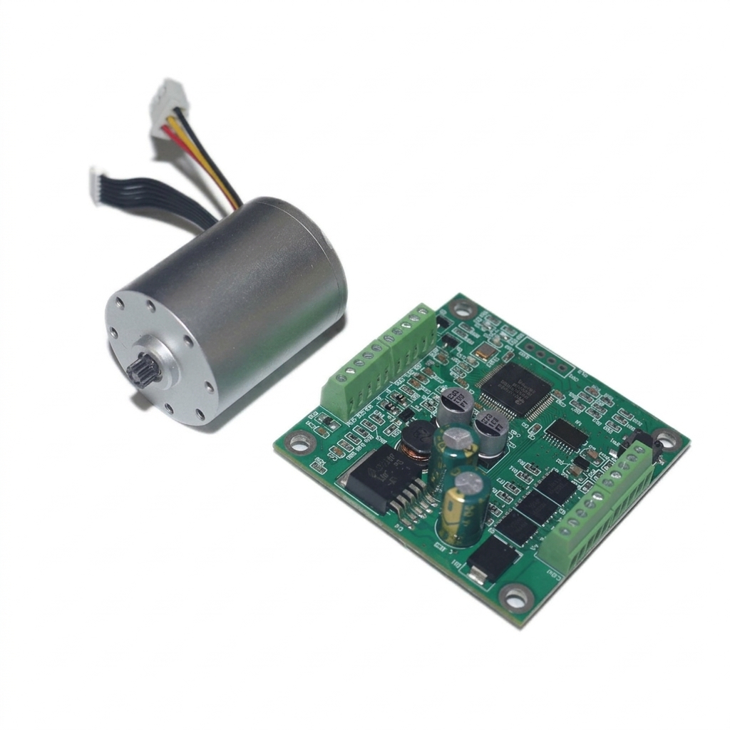
Motor and External Controller Illustration
The image shows a motor and a separate controller board. It does not establish the board's control algorithm, dimensions, thermal rating, or suitability for integration into the motor housing.
3. Electromagnetic Interference (EMI) & Cabling Realities
Shorter phase connections can simplify electromagnetic compatibility (EMC) work. Whether that benefit matters depends on switching edges, cable routing, grounding, enclosure construction, and the applicable end-product requirements.
The High dV/dt Radiation Problem in Discrete Systems
A brushless motor driver switches phase voltage using PWM. The edge rate and resulting noise are device- and layout-dependent.
With an external driver, longer phase cables can increase common-mode emissions and ringing. Assess shielding, bonding, filtering, and switching slew rate on the actual harness. Reflected-wave stress depends on cable propagation time relative to switching rise time; bearing-current damage should not be assumed for every miniature low-voltage motor.
What Integration Changes
Integration shortens the phase interconnect and may reduce its radiating loop area. The DC supply and communication cables can still carry switching noise. Decoupling, grounding, and enclosure bonding remain important; see TI's layout guide, sections 1 and 5.
Integration does not guarantee an EMC pass or eliminate bearing currents. Agree the applicable end-product standard, test configuration, harness, grounding, and acceptance limits with the responsible compliance team. A motor or driver document alone does not certify the finished machine.
4. Multi-Axis Synchronization & Bus Latency
While integrated motors simplify physical cabling, they introduce a digital control challenge: motion synchronization over a shared bus.
[Trajectory Master / PLC]
           │
      Shared CAN-FD Bus (configured bit rates)
    ┌──────┴──────────┬──────────────┐
    ▼                 ▼              ▼
[Joint 1 Motor]  [Joint 2 Motor]  [Joint 3 Motor]
(Local Position) (Local Position) (Local Position)
The Communication Bottleneck
Separate the PWM carrier, local current-loop update, host setpoint rate, and closed-loop bandwidth. They are different quantities. A centralized implementation may synchronize sampling and PWM through shared hardware, but it still has computation and sampling delay. A networked drive can close fast local loops while receiving slower trajectory commands.
Neither CAN-FD bit rate nor a motion-profile label guarantees a particular axis update rate or path accuracy. Estimate utilization as axes × frames_per_axis_per_cycle × worst_case_frame_bits × cycles_per_second / bus_bit_rate, then account for arbitration, stuffing, retries, and diagnostics. For CAN-FD, budget arbitration and data phases at their separate configured rates. Measure worst-case command age, clock alignment, and lost-frame behavior with all nodes active before accepting the architecture.
5. Total Cost of Ownership (TCO) & The Dual-Failure Scrap Risk
Hypothetical cost example in USD, not a quotation or market benchmark: an integrated assembly costs $140; a motor at $70 plus an external driver at $45 costs $115. The integrated piece-price premium is $25.
However, evaluating Total Cost of Ownership (TCO) requires analyzing harness production, cabinet volume, assembly labor, and warranty scrap rates.
Installed-Cost Break-Even
Assume the external architecture adds $18 per axis in harness and connectors and $12 in assembly/test labor. Assume the integrated option adds $8 and $5 respectively. Installed cost is then $145 external versus $153 integrated. Under these assumptions, integration saves $17 in harness/labor but remains $8 more expensive per axis. It breaks even only if further net savings exceed $8, such as enclosure or installation savings. Actual harness drawings and labor estimates must replace these inputs.
For six Hall-sensored motors, 6 × 8 = 48 conductors is a sum of individual motor-cable conductors, not the count through every joint. A four-core daisy chain uses four core conductors per segment; trunk current, voltage drop, branch connectors, safety wiring, and segment count still matter. Compare cable length, cross-section, termination count, and flex life rather than claiming a fixed percentage saving.
The Dual-Failure Scrap Rate Dilemma
Separate motor and driver modules may allow replacing only the failed part, but electrical faults can damage both. A sealed integrated module may require whole-unit replacement, while a serviceable design may permit board or bearing repair. Neither outcome follows from architecture alone.
Model lifetime cost as installed cost + energy cost + expected service cost + downtime + spare inventory, using the same service horizon. Obtain repair policy, warranty coverage, replacement labor, and failure-rate evidence from the supplier. Do not turn an assumed failure rate into a claimed field result. Request comparable motor-plus-driver quotations against the same load profile and validation scope.
6. Comprehensive Engineering & Procurement Comparison Matrix
The table below contrasts the technical, operational, and financial dimensions across both architectures:
| Evaluation Dimension | Integrated FOC Smart Micro BLDC | Discrete Micro BLDC + External ESC | Engineering & Procurement Impact |
|---|---|---|---|
| Wiring & Interconnect Bulk | Example: 4 power/bus conductors, plus auxiliaries | 3 phase leads; 8 total with basic Hall feedback; encoder pinout varies | Compare actual pinouts, flex routing, and connector count. |
| Cabinet / Enclosure Space | Driver occupies motor-end volume | Driver occupies separate board or enclosure space | Check total envelope and cooling clearance, not motor diameter alone. |
| Continuous Torque Capacity | Limited by coupled motor and electronics temperatures | Motor and driver can have separate cooling paths | Request assembly-level torque-speed and temperature-rise data. |
| EMI / EMC | Short phase connections may help; supply/bus noise remains | Phase cable routing may need added mitigation | Validate the final machine and harness; no automatic compliance advantage. |
| Shaft Voltages & Bearing Currents | Shorter leads do not remove all common-mode coupling | Risk depends on voltage, edge rate, cable, and motor construction | Investigate relevant symptoms before specifying bearing remedies. |
| Multi-Axis Synchronization | Requires suitable local loops and network timing | Shared hardware or networked control is possible | Measure latency, jitter, and fault recovery at full node count. |
| Thermal Operating Ambient | Whole assembly must meet its documented range | Motor and remote driver each need qualified ranges | There is no architecture-wide 70°C cutoff. |
| Firmware Ownership & Tuning | Depends on vendor API, access, and licensing | Depends on whether the driver is proprietary or OEM-designed | Specify parameter access, version control, and update recovery. |
| Field Service & Repairability | Sealed units may require whole-module replacement | Separate replacement may be possible; faults can affect both | Obtain a repair and spare-parts policy. |
| BOM Unit Cost | Quote the complete configured assembly | Quote motor, driver, feedback, and harness consistently | Compare equivalent scope, volume, and test requirements. |
| Total Lifetime Cost | May save wiring and assembly work | May reduce repair cost or reuse existing electronics | Use the explicit cost model above; no universal TCO winner. |
7. Operational Boundaries: When NOT to Use Integrated FOC Drivers
Treat these conditions as qualification gates. A standard integrated unit should not be assumed suitable without supporting evidence:
- Sterilization or aggressive cleaning: Specify the actual temperature, pressure, chemicals, cycle duration, and lifetime cycle count. Separating electronics may help, but the motor, bearings, seals, and cabling still require qualification for the process.
- High ambient or limited cooling: Compare required operating temperatures with the complete assembly rating and hotspot measurements. An external driver helps only if its own mounting and the motor's cooling are adequate.
- Shock and vibration: Specify acceleration, pulse shape, duration, frequency spectrum, mounting, and powered state. A single G value cannot establish PCB, encoder, or bearing survivability.
- Simple fixed-speed loads: Compare startup torque, minimum speed, noise, efficiency, and cost before paying for a networked positioning drive. A simpler sensorless driver may suffice, including a compact FOC IC; external packaging is not inherently cheaper.
8. Sourcing & Engineering Qualification Checklist
Before issuing a Purchase Order (PO) or freezing CAD geometry around an integrated micro BLDC motor, the OEM engineering and sourcing team should complete this 10-point qualification audit:
- 1. Thermal Dissipation Path Verified: Are stabilized winding, case, and driver hotspot results available at the required load, ambient, mounting, and airflow, with model assumptions stated?
- 2. Component Derating Audit: Are operating limits and temperature margins documented for power devices, sensors, capacitors, and connectors, separately from absolute maximum ratings?
- 3. Communication Protocol Alignment: Are physical layer, message profile, control modes, and host compatibility specified separately (for example, CAN-FD versus a CANopen/CiA 402 implementation)?
- 4. Bus Latency & Cycle Rate Tested: Does the complete node count meet the project's update period, worst-case jitter, and packet-loss requirements under full traffic?
- 5. In-Factory Parameter Configuration: Does the supplier offer factory pre-flashing of current limits, PID gains, encoder offset calibration, and node IDs to streamline your production line?
- 6. Ingress Protection (IP Rating): Is the required IP rating supported by testing of the assembled motor, including shaft, connectors, and cable entries? Coating or potting alone does not establish an IP rating.
- 7. Supply Chain Transparency: Are lifecycle support, change notification, approved substitutions, last-time buys, and component traceability agreed for the program's service life?
- 8. Fault Response and Safety: Are bus-loss, brownout, overcurrent, and regeneration responses tested? If STO is required, is its safety capability documented separately from ordinary enable or fault-disable inputs?
- 9. Feedback Accuracy: Is encoder error measured over temperature, speed, load current, and assembly tolerances, including any necessary calibration or shielding?
- 10. Dual-Failure Warranty Modeling: Has procurement factored the full replacement scrap cost into warranty reserves and spare-parts logistics?
9. Frequently Asked Questions (FAQ)
Q1: Can an integrated FOC micro BLDC motor match the peak acceleration of a discrete motor?
It can, if the complete assembly supports the required peak phase current and voltage. Check pulse duration, initial temperature, repetition rate, current limiting, magnet limits, and inverter capability. A one- or two-second demand is not automatically thermally safe; the driver can reach its limit before the winding does.
Q2: How does an integrated driver handle encoder alignment?
For a sensored drive, the supplier may calibrate the electrical angle offset and store it in non-volatile memory. Ask for the calibration procedure, accuracy limits, and recalibration requirements after repair. Sensorless FOC has different startup and rotor-estimation requirements; the word FOC does not imply an encoder is present.
Q3: What happens if the communication bus cable is severed during robotic operation?
The response depends on the implemented timeout and fault state: the drive may coast, perform a controlled stop, or command a mechanical brake. Confirm behavior by testing a severed cable and a host that stops sending commands. Dynamic short-circuit braking does not provide static holding torque at zero speed. Gravity-loaded axes may need a suitable mechanical holding brake. An ordinary watchdog or enable input is not evidence of certified STO.
Q4: Are integrated FOC motors more vulnerable to electrical over-stress (EOS) from regenerative braking?
Both architectures can raise the DC bus voltage during deceleration. Risk depends on returned energy, supply sink capability, shared bus capacitance, voltage limits, and any brake resistor or shunt. A centralized drive does not necessarily include a brake chopper. ST AN1625, section 2.3 discusses bulk-capacitor selection and supply rise during braking. Evaluate all axes that may decelerate together.
Q5: How do we update driver firmware on integrated motors installed inside a completed machine?
Only if the selected product supports a suitable bootloader or update interface. Specify firmware access, version identification, update authorization, power-loss recovery, rollback, and whether a service connector is needed. Parameter storage and firmware replacement are different capabilities; neither is guaranteed by an integrated housing.
Q6: What is the typical lead-time and MOQ impact when procuring integrated smart motors compared to catalog motors?
There is no reliable architecture-wide MOQ or lead-time range. Catalog stock, PCB availability, winding changes, firmware development, test fixtures, and validation scope can dominate either option. Request dated quotations with prototype quantity, production volume, non-recurring engineering cost, sample lead time, production lead time, and revision-controlled acceptance criteria.
10. Summary & Sourcing Next Steps
Selecting between an integrated FOC micro BLDC motor and a discrete motor/ESC architecture is not merely a component choice—it defines the physical packaging, thermal budget, wiring harness reliability, and maintenance economics of your entire product.
- Choose Integrated FOC Micro BLDC Motors when:
- You are designing multi-axis articulated robots, surgical arms, or compact pan-tilt systems where cable thickness and joint routing space are severe bottlenecks.
- Short phase connections are valuable and the final assembly can be validated for its required EMC performance.
- The assembly-level thermal rating, protocol, calibration, and repair policy meet your requirements.
- Choose Discrete Micro BLDC Motors when:
- Separating motor and driver cooling is necessary to meet the validated continuous load.
- Electronics need to remain outside a cleaning, heat, or vibration zone, with the motor separately qualified for that environment.
- You need access to a suitable external drive or your own control implementation.
- Low-cost, modular repairability and isolated spare-parts economics take precedence over wiring bulk.
OEM RFQ Blueprint
To accelerate engineering review and quote turnaround for your actuator program, copy and paste this specification block into your inquiry:
Project / Application: [e.g., 6-Axis Miniature Surgical Manipulator Joint]
Actuator Architecture: [Integrated FOC Smart Motor / Discrete Motor + External Drive]
Form Factor Limit: [Max Outer Diameter (e.g., 16mm, 22mm, 28mm) x Max Length]
Rated Operating Voltage: [e.g., 24VDC or 48VDC Battery/Bus]
Continuous Torque & Speed: [e.g., 35 mNm at 3,500 RPM]
Peak Torque & Duration: [e.g., 90 mNm for 1.5 seconds]
Communication / Profile: [e.g., CAN-FD with specified messages / RS-485 Modbus RTU]
Control Mode & Timing: [Speed / torque / position; node count; update period; jitter]
Target Feedback Resolution: [e.g., 14-bit or 16-bit Absolute Magnetic Angle]
Ambient Temperature Range: [e.g., -10°C to +55°C]
Ingress Protection (IP Target): [e.g., IP54 or IP65]
Mounting & Duty Cycle: [Cooling path; airflow; load timeline; starts per hour]
Fault & Regeneration Needs: [Bus loss; holding brake; returned energy; bus limit]
Validation Evidence: [Thermal; EMC; feedback accuracy; cleaning/shock if applicable]
Volume: [Prototype quantity; annual production volume; service horizon]
Use these example fields as requirements to review, not as advertised product ratings. Contact the Micro BLDC team with your completed RFQ to discuss feasible configurations, available validation evidence, sample scope, and a dated quotation.
11. Sources and Evidence Limits
- Texas Instruments, SLVA959B, revised October 2021: Best Practices for Board Layout of Motor Drivers. Sections 1, 2, and 5 cover grounding, thermal layout, and decoupling. The URL retains an older revision suffix; the retrieved PDF identifies revision B.
- Texas Instruments, SLLSFI0C, revised June 2023: MCF8316A Sensorless Field Oriented Control (FOC) Integrated FET BLDC Driver. Sections 6 and 10.3 provide device-specific limits and thermal information. This is a sensorless driver IC, not a networked positioning motor or a recommendation for every voltage in the RFQ example.
- STMicroelectronics, AN1625, October 2003: L6235 Three Phase Brushless DC Motor Driver. Sections 2.3 and 2.13 discuss bulk capacitance and power management. This Hall-commutated driver is a design reference, not proof of a modern integrated FOC assembly's performance.
These manufacturer documents support component-level design principles. They do not establish a universal torque derating, EMC certification, safety certification, field failure rate, procurement lead time, or TCO saving. The architecture comparison and worked examples are editorial screening aids; final selection requires project-specific supplier evidence and system validation.
Author

Categories
More Posts
Sensorless vs. Hall Sensor vs. Magnetic Encoder for Micro BLDC Motors: Low-Speed Stability, Starting Torque Under Load, Wiring Overhead, and OEM Sourcing Guide
Micro BLDC feedback selection: compare sensorless, digital Hall and magnetic encoders by torque ripple, low speed and wiring. Use the checklist for OEM RFQs.
Micro BLDC Gearhead Selection: Miniature Planetary vs. Spur vs. Strain Wave Reducers — Speed Limits, Backlash, Efficiency, and OEM Sourcing
Micro BLDC gearhead selection: compare planetary, spur and strain wave reducers by speed, backlash and efficiency. Use the checklist to prepare your OEM RFQ.
Micro BLDC Motor Sizing Guide for Compact Robotics
A practical engineering guide on calculating RMS torque, gear ratio efficiency, and thermal limits when specifying micro BLDC gear motors for robotic joints and grippers.