Micro BLDC LogoMicro BLDC
Start inquiry
Micro BLDC LogoMicro BLDC
WhatsApp
Micro BLDC LogoMicro BLDC

Precision Micro BLDC Motor Engineering, Validation, and Manufacturing Support.

Inquiry Email

[email protected]

Email app

Include motor type, OD, voltage, speed, load, quantity, and destination.

Instant Chat

+86 18857971991

Chat on WhatsApp

Direct RFQ follow-up from our engineering team.

Products
  • Micro BLDC Motors
  • Micro Brushless DC Motors
  • Custom OEM Assemblies
  • Coreless Micro BLDC Motors
  • Slotless Micro BLDC Motors
  • Low Noise Medical Micro BLDC
  • Medical Slotless Micro BLDC
  • Long Life Micro BLDC Motors
  • High Speed Drone Micro BLDC
  • Ultra-Light FPV & UAV Micro BLDC
  • Hall & Encoder Micro BLDC
  • Sensorless Micro BLDC Motors
  • Integrated FOC Micro BLDC
  • Micro BLDC Gear Motors
Solutions
  • Medical Devices
  • UAV and Drone
  • Compact Appliances
  • Robotics
  • Precision Instruments
OEM Capabilities
  • Capabilities & Compliance
  • Custom Micro BLDC Engineering
  • Manufacturing Capabilities
  • Noise & Lifetime Validation
  • Quality & Inspection
  • Compliance & IP Protection
  • Distributor & Sourcing Support
Resources
  • Blog
  • About
  • Contact / RFQ
  • Privacy Policy
  • Cookie Policy
  • Terms of Service
© 2026 Micro BLDC. All Rights Reserved.|Backed by Linkup Ai Co., Ltd. Manufacturing delivered by the Advanced Manufacturing Division of Linkup Precision.|Legal entity: Linkup Ai Co., Ltd.
← Back to Products

Integrated FOC Micro BLDC Motors

Micro BLDC motor and driver integration support for compact OEM devices that need quiet soft-start behavior, simplified wiring, speed control, current limiting, and field-oriented control without a large external controller board.
Target Buyer:Best for electronics and mechanical teams that want the motor, driver, wiring, firmware interface, and validation boundary reviewed together instead of buying a bare motor and solving control later.
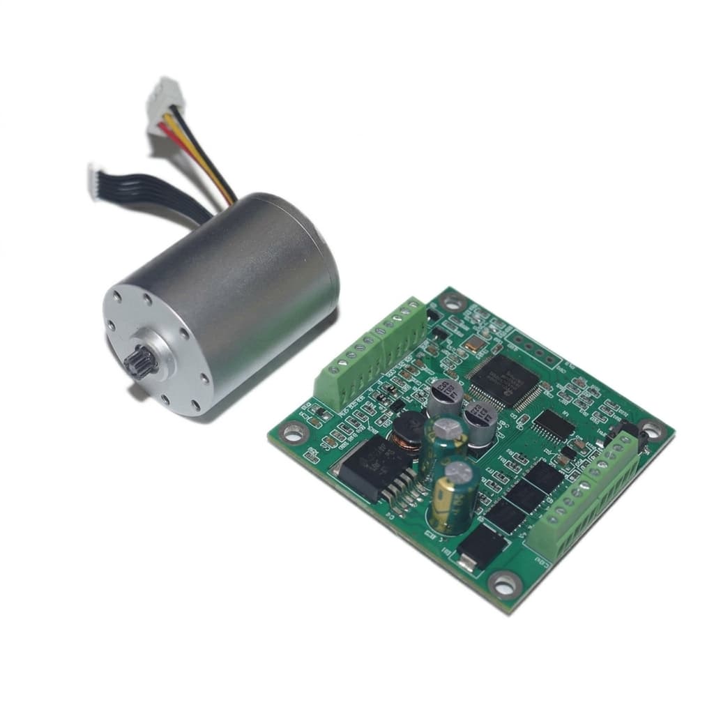
Micro BLDC motor with matched controller board for FOC integration review

Controlled technical documents

Request datasheet, CAD, and validation scope for Integrated FOC Micro BLDC Motors

Public generic files can mislead OEM selection when winding, bearing, connector, test fixture, or acceptance criteria are still open. Technical documents are shared after model, revision, NDA, test condition, and destination scope are confirmed.

Request by WhatsAppSend full RFQ

No placeholder certificates, stock proof photos, or generic public CAD downloads are published from this request block.

Datasheet fit check

Voltage, speed, torque, current, thermal, and life targets.

CAD or drawing review

Shaft, flange, connector, cable, and assembly interface.

Validation evidence scope

Noise, load, vibration, endurance, and inspection records.

Capability Highlights

  • Motor-plus-driver integration review for compact PCB, cable-limited, or enclosure-constrained devices
  • Sensorless FOC, Hall-assisted FOC, PWM, analog, UART, and custom command interfaces reviewed by project
  • Soft-start, current limit, speed loop, acoustic tone, EMI, and temperature-rise validation planning

Typical Applications

  • Quiet pumps and blowers
  • Portable medical devices
  • Precision instruments
  • Premium compact appliances

Engineering Focus

  • Define whether the driver is integrated on-motor, nearby on a harnessed PCB, or supplied as a matched controller module
  • Match commutation method, current limit, PWM frequency, speed command, protection logic, and load startup requirement
  • Validate acoustic tone, soft-start, temperature, EMI, and speed stability inside the buyer enclosure

Buyer Decision Notes

Best-fit buyer

Best for electronics and mechanical teams that want the motor, driver, wiring, firmware interface, and validation boundary reviewed together instead of buying a bare motor and solving control later.

Validate Before Sampling

  • Define whether the driver is integrated on-motor, nearby on a harnessed PCB, or supplied as a matched controller module
  • Match commutation method, current limit, PWM frequency, speed command, protection logic, and load startup requirement

RFQ Data That Changes the Quote

  • Motor size, voltage, load, speed range, startup torque, duty cycle, and enclosure thermal path
  • Preferred control interface such as PWM, analog voltage, UART, I2C, enable, direction, or tach output
  • Sensorless FOC, Hall-assisted FOC, encoder, or open-loop/six-step comparison needs

Selection, Validation, and Production Flow

StageBuyer InputFactory / QC CheckpointDecision Output
RFQ feasibility reviewMotor size, voltage, load, speed range, startup torque, duty cycle, and enclosure thermal path; Preferred control interface such as PWM, analog voltage, UART, I2C, enable, direction, or tach outputDefine whether the driver is integrated on-motor, nearby on a harnessed PCB, or supplied as a matched controller moduleFeasibility notes, missing parameters, and sample direction.
Sample definition and validationSensorless FOC, Hall-assisted FOC, encoder, or open-loop/six-step comparison needs; PCB space limit, connector, cable, IP rating, EMC constraints, protection logic, and required documentationControl interface: PWM, analog voltage, UART, I2C, enable, direction, tach, or project-specific command setControlled sample scope with measurable acceptance criteria.
Pilot lot and repeat productionPrototype quantity, annual volume, target price range, validation tests, and timelineIntegrated driver overheats inside the final enclosure: Check driver current, copper area, airflow, heat sink path, duty cycle, ambient temperature, and motor winding temperature before pilot approval.Pilot records tied to pcb and harness reduction and outgoing inspection.

Key Evaluation Matrix

MetricTypical RangeWhy It Matters
Control interfacePWM, analog voltage, UART, I2C, enable, direction, tach, or project-specific command setA pre-agreed command interface can reduce firmware work for the buyer and prevent late controller mismatch.
PCB and harness reductionCompared case-by-case against the buyer external ESC or controller layout after drawing reviewSpace savings are real only when the driver location, connector, protection parts, heat path, and EMI rules are compared against the full device layout.
Soft-start and acoustic behaviorStartup ramp, current ripple, PWM/FOC settings, load, enclosure, and dBA method defined per projectIntegrated control is valuable when it lowers startup shock, tonal noise, and application-side tuning effort.

RFQ Checklist

  1. Motor size, voltage, load, speed range, startup torque, duty cycle, and enclosure thermal path
  2. Preferred control interface such as PWM, analog voltage, UART, I2C, enable, direction, or tach output
  3. Sensorless FOC, Hall-assisted FOC, encoder, or open-loop/six-step comparison needs
  4. PCB space limit, connector, cable, IP rating, EMC constraints, protection logic, and required documentation
  5. Prototype quantity, annual volume, target price range, validation tests, and timeline

Risk Controls

  • Integrated driver overheats inside the final enclosure: Check driver current, copper area, airflow, heat sink path, duty cycle, ambient temperature, and motor winding temperature before pilot approval.
  • Code-free control promise exceeds the actual driver interface: Define the exact command method, default firmware behavior, speed range, acceleration ramp, protections, and change process before sampling.
  • FOC motor sample passes on the bench but creates EMI issues in the device: Review grounding, cable length, shielding, PWM frequency, filtering, enclosure, and sensitive sensor placement during validation.

Requestable Evidence Pack

Ask for proof tied to the exact test condition

Use this evidence package to keep motor claims connected to load, fixture, controller, drawing revision, and acceptance criteria before sampling or production release.

RFQ note

Do not treat quiet, long-life, efficient, or compliant as a generic claim. Confirm the measured condition, buyer fixture, sample lot, and acceptance rule for this program.

Controlled specification sheet

Locks the motor envelope, voltage, speed, load, shaft, connector, and revision basis before quote comparison.

Request status
Buyer input required - Prepared after envelope and electrical targets are fixed
Buyer input
Motor envelope, voltage range, target RPM or KV, load point, shaft, connector, quantity, and revision owner.
Supplier record
Model direction, controlled spec summary, drawing revision note, and open engineering questions.
Asset owner
Applications engineering - controlled-specification-sheet

Electrical and load test matrix

Keeps current, speed, torque, power, and temperature claims tied to the real test condition.

Request status
Buyer input required - Generated from agreed load and thermal condition
Buyer input
No-load and load points, thermal limit, duty cycle, ambient temperature, and acceptance criteria.
Supplier record
No-load/load current, speed, torque or load behavior, temperature rise, and sample identification.
Asset owner
Test engineering - load-thermal-data

Noise and vibration validation plan

Prevents low-noise claims from being detached from fixture, distance, controller, load, and device resonance.

Request status
Buyer input required - Requires fixture, load, controller, and dBA distance
Buyer input
dBA target, test distance, mounting method, controller mode, load condition, and vibration-sensitive interface.
Supplier record
Noise method, vibration or balance check, sample lot, mounting condition, and measured result summary when available.
Asset owner
Validation engineering - noise-vibration-test-method

Lifetime and duty-cycle plan

Turns long-life wording into hours, cycles, environment, load, and failure criteria that can be reviewed.

Request status
Buyer input required - Scoped after life hours, cycles, and failure criteria
Buyer input
Target hours, start-stop cycles, duty profile, temperature, humidity, load, and end-of-test limits.
Supplier record
Validation plan, interim checks, failure criteria, and project-specific life-test summary when arranged.
Asset owner
Reliability engineering - lifetime-validation-plan

Attach these inputs to reduce quote loops

  • Motor size, voltage, load, speed range, startup torque, duty cycle, and enclosure thermal path
  • Preferred control interface such as PWM, analog voltage, UART, I2C, enable, direction, or tach output
  • Sensorless FOC, Hall-assisted FOC, encoder, or open-loop/six-step comparison needs
  • PCB space limit, connector, cable, IP rating, EMC constraints, protection logic, and required documentation

Inquiry Email

[email protected]

Email evidence request

Opens with the evidence checklist and buyer inputs prefilled.

Instant Chat

+86 18857971991

WhatsApp evidence request

Use when you need a quick document-scope check before a full RFQ.
Product Gallery

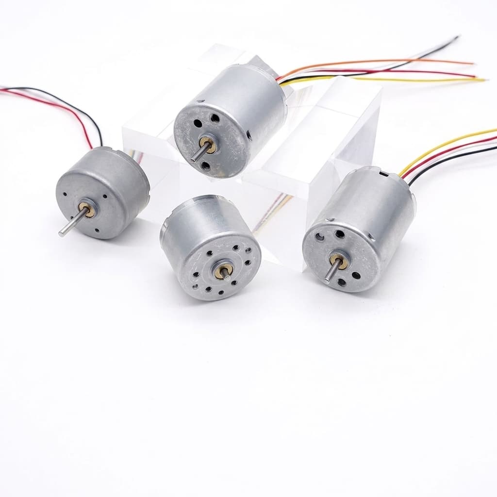
Compact brushless motor controller module for integrated driver planning

Buyer FAQ

Can you supply a micro BLDC motor with an integrated FOC driver?

Integrated or matched driver scope can be reviewed when the motor envelope, voltage, load, control interface, PCB space, thermal path, EMI constraints, and quantity plan are clear.

Can the motor be controlled without custom firmware?

Code-free control is possible only when the driver firmware and command interface are preconfigured for the buyer speed, direction, ramp, protection, and feedback needs.

Related Resources

  • Sensorless Micro BLDC Motors
  • Hall and Encoder Micro BLDC Motors
  • Custom OEM Micro BLDC Assemblies
  • Custom Micro BLDC Engineering
  • Contact / RFQ

Inquiry Email

[email protected]

Email app

Include motor type, OD, voltage, speed, load, quantity, and destination.

Instant Chat

+86 18857971991

Chat on WhatsApp

Direct RFQ follow-up from our engineering team.