
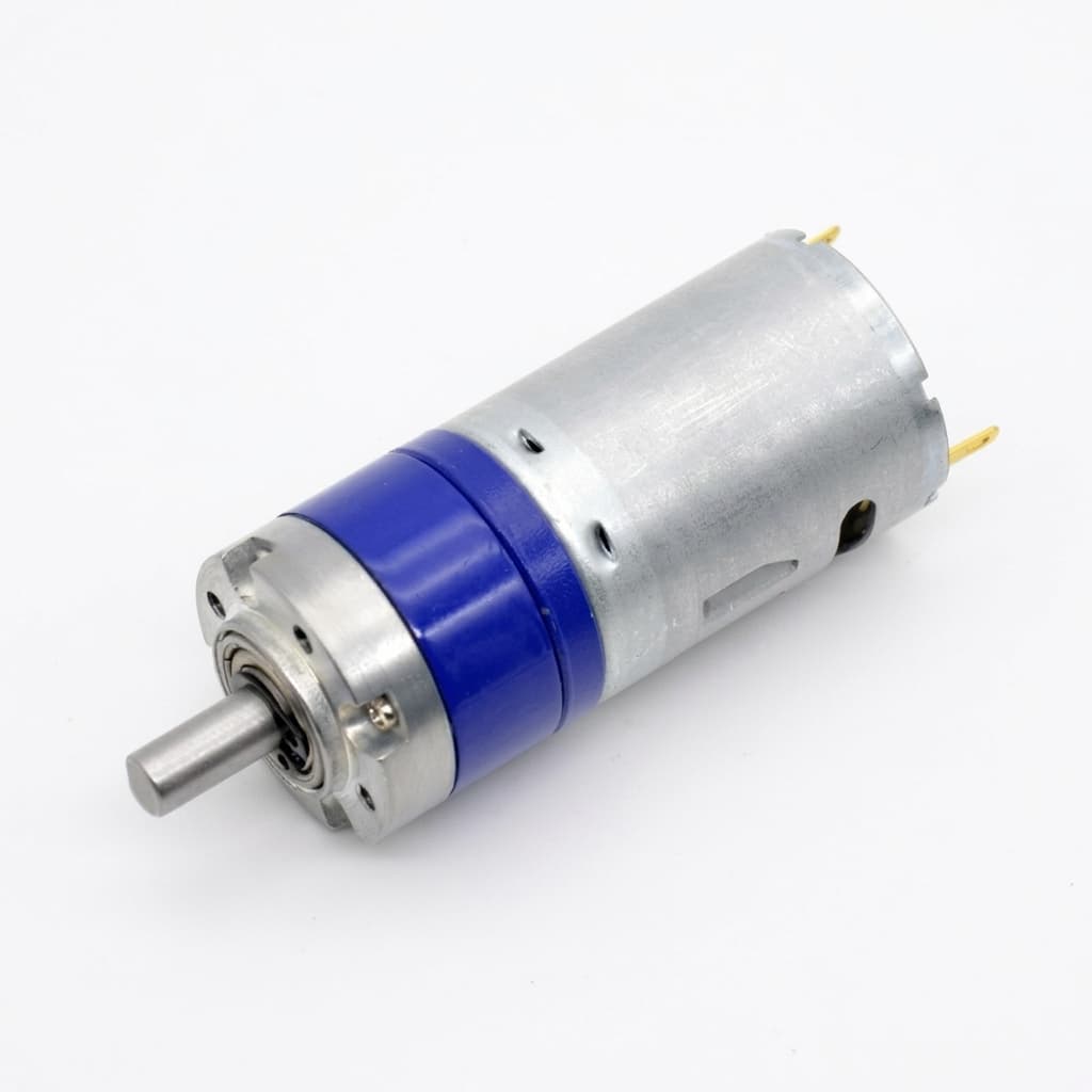
Micro BLDC Gearhead Selection: Miniature Planetary vs. Spur vs. Strain Wave Reducers — Speed Limits, Backlash, Efficiency, and OEM Sourcing
Micro BLDC gearhead selection: compare planetary, spur and strain wave reducers by speed, backlash and efficiency. Use the checklist to prepare your OEM RFQ.
Micro BLDC gearhead selection starts with the required output torque, output speed, duty cycle, and positioning error budget. Choose an architecture only after those requirements fit the ratings of a specific motor-and-gearhead combination. A motor's maximum speed does not establish the gearbox's permissible input speed.
Quick decision:
- Favor a miniature spur gearhead when low starting drag, cost, and flexible shaft placement matter. Confirm that its torque and bearing ratings cover the load.
- Favor a miniature planetary gearhead when concentric packaging and compact torque transmission matter. Compare stage count, efficiency, input speed, and measured reversal play; precision and high-speed versions are separate specifications.
- Favor a miniature strain wave reducer when high single-stage reduction and a zero-backlash design are valuable. Check lost motion, transmission accuracy, torsional stiffness, input speed, and total assembly cost separately.
Published and last reviewed: 29 October 2026. Scope: global OEM engineering and procurement of miniature BLDC assemblies, with a target envelope up to 32 mm outer diameter and a nominal supply up to 48 VDC. Not every architecture is available at every diameter. This is a selection framework, not a component approval or a medical, automotive, or aerospace qualification.
Method and evidence: compare the named manufacturer references in Sources with the required operating points, then calculate motor demand and losses. All worked examples below use stated assumptions; they are reproducible calculations, not bench measurements, customer results, or supplier guarantees. Model-specific ratings take precedence over architectural generalizations.
For an initial feasibility review, send your torque, speed, envelope, and duty-cycle requirements.
1. Kinematic and Architectural Comparison
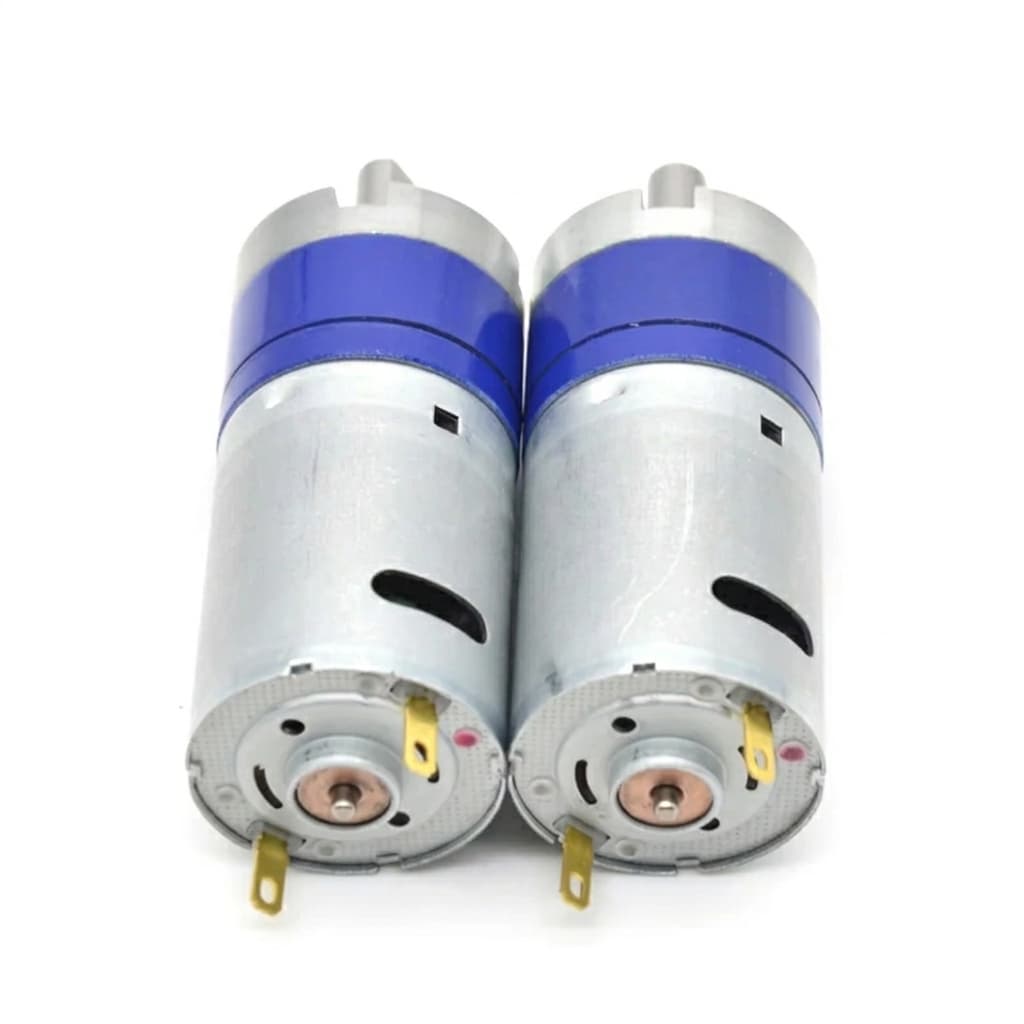
These conceptual layouts show how the motor connects to the load. For the available motor-and-gearbox integration scope, see Micro BLDC gear motors.
Conceptual layouts, not dimensioned gear profiles or product ratings. Spur: offset shafts; planetary: concentric load sharing; strain wave: elastic tooth engagement. Verify speed, torque, bearing support, and backlash for the exact assembly.
1.1 Miniature Spur Gearheads: Low Drag and Flexible Packaging
A spur train transfers motion through pairs of gears on parallel shafts. Several stages may be combined, and input and output need not share a centerline. A gear pair can have more than one tooth pair in contact; “one transmission point per train” does not mean exactly one tooth always carries the entire load.
Check tooth material, dimensions, bearing support, and ratio before accepting a torque rating. There is no universal 0.3 Nm ceiling for spur gearheads. An offset shaft can also be useful when the mechanism cannot sit directly behind the motor.
1.2 Miniature Planetary Gearheads: Concentric Torque Transmission
In a common fixed-ring arrangement, the motor drives the sun, the planets share load, and the carrier provides the output. Load sharing depends on manufacturing and assembly tolerances; three planets do not guarantee three times the torque of any particular spur gearbox.
Multiple stages increase reduction and introduce additional losses and clearances. Reduced-backlash, high-speed, and reinforced versions solve different requirements; one designation does not establish the other ratings.
1.3 Miniature Strain Wave Reducers: Backlash Is One Part of Accuracy
A wave generator elastically deforms a flexspline into engagement with a circular spline. Harmonic Drive's technology explanation describes this mechanism and its zero-backlash design. Harmonic Drive is a trademark; strain wave is the architecture.
A zero-backlash rating does not mean zero elastic deflection, zero hysteresis, or zero transmission error. Ask for the exact model's lost-motion and stiffness data at the intended load. A component set may also require separate output bearings and housing; do not assume an integrated cross-roller bearing or a complete actuator is included.
2. BLDC Motor RPM vs. Gearhead Input Speed Limits
Calculate n_input = ratio × n_output at the fastest commanded output speed, including overshoot. Compare it with the selected gearhead's continuous and intermittent ratings under the actual load, lubrication, ambient temperature, and mounting conditions. A micro BLDC motor must deliver the required torque at that input speed within its own thermal limits.
2.1 Published Model Examples, Not Architecture-Wide Ceilings
The following six entries are from Portescap's gearhead overview, checked on 29 October 2026. The diameter column is the manufacturer's motor diameter field, not a verified gearbox envelope drawing.
| Listed model and bearing version | Listed motor diameter (mm) | Maximum recommended input speed (rpm) |
|---|---|---|
| B16, ball bearing | 16 | 8,000 |
| K27, ball bearing | 27 | 4,000 |
| R16, sleeve bearing | 16 | 7,500 |
| R22, ball bearing | 22 | 5,000 |
| R22HT, ball bearing | 22 | 12,000 |
| R26HT, ball bearing | 22 | 18,000 |
These are screening references, not interchangeable products or proof of continuous operation in your application. Select the exact ratio and execution, then obtain its torque-speed, temperature, and life limits. Do not treat the overview's static torque field as continuous output torque. Specialized high-speed designs also exist; a universal 15,000 rpm rejection rule would exclude valid candidates.
2.2 Use the Speed Limit to Bound the Ratio
Illustrative requirement: output speed 120 rpm; proposed gearhead continuous input limit 6,000 rpm. The largest allowable ratio on speed alone is 6,000 / 120 = 50:1. A 100:1 option would require 12,000 rpm and fails this screening condition, even if its output torque looks attractive. A ratio at or below 50:1 still needs torque, thermal, and overshoot checks.
High input speed can increase lubricant, bearing, and mesh losses. Pitch-line speed for a fixed-axis pinion is v = π × d × n / 60, with pitch diameter d in metres and n in rpm. A 3 mm pinion at 30,000 rpm gives 4.71 m/s. In planetary gearing, relative mesh speed also depends on carrier motion. Neither calculation predicts grease starvation or hours to failure by itself.
If the intended input speed exceeds the rating, reduce commanded speed, change the ratio or winding, or qualify a gearhead explicitly rated for that operating point. Ceramic components or a particular grease chemistry alone do not establish a speed rating.
3. Efficiency Compounding and the Thermal Loss Penalty
3.1 A Stage-Loss Sensitivity Calculation
For sequential stages, η_total = η_1 × η_2 × ... × η_N. Using the same efficiency for every stage is a simplifying assumption. The table compares two assumed per-stage efficiencies; 0.75 is a sensitivity case, not a measured cold-temperature value or a worst-case guarantee.
| Stage count | Total efficiency at assumed 0.85 per stage | Total efficiency at assumed 0.75 per stage | Motor torque factor vs. lossless gearing at 0.85 per stage |
|---|---|---|---|
| 1 | 85.0% | 75.0% | 1.18× |
| 2 | 72.3% | 56.3% | 1.38× |
| 3 | 61.4% | 42.2% | 1.63× |
| 4 | 52.2% | 31.6% | 1.92× |
The factor is 1 / η_total at the same ratio and load; it is not a motor frame-size multiplier. If a datasheet already gives total efficiency for the selected ratio, use that value without compounding it again. At startup, use breakaway torque rather than a steady-running efficiency model.
3.2 Worked Motor Torque and Power Example
Assume a mechanism needs 1.2 Nm at 30 rpm, with a proposed 100:1 reduction and three stages each operating at 0.82 efficiency. These are hypothetical inputs, not ratings of the products above.
Total efficiency = 0.82^3 = 0.551368
Motor speed = 100 × 30 = 3,000 rpm
Motor torque = 1.2 / (100 × 0.551368) = 0.02176 Nm = 21.8 mNm
Output power = 1.2 × (2π × 30 / 60) = 3.77 W
Mechanical input power = 3.77 / 0.551368 = 6.84 W
Gearbox loss = 6.84 - 3.77 = 3.07 W
The speed and torque conversions follow maxon's gear selection reference, printed pages 72–73. The scenario and loss arithmetic are our illustrative analysis. Assuming 90% total efficiency instead would underestimate motor torque as 13.3 mNm. This difference warrants a new operating-point check; it does not predict a specific shutdown time.
The gearhead must independently support 1.2 Nm continuously and any acceleration or braking peaks. Electrical input will exceed 6.84 W because motor and controller losses are additional. Check motor continuous torque at 3,000 rpm, not just stall torque.
3.3 Housing Temperature Requires an Actual Thermal Path
A simple steady-state estimate is temperature rise = loss power × housing-to-ambient thermal resistance. For assumed values of 2.5 W and 25 K/W, the rise is 62.5°C. The 25 K/W value is not a generic rating for a 16 mm gearbox.
Verify thermal resistance or stabilized temperature in the intended housing, mounting, airflow, ambient, and duty cycle. Heat also travels through the motor flange and load structure; this one-node estimate cannot establish winding, magnet, or lubricant temperatures.
If efficiency or bearing limits remain unknown, request a motor-and-gearhead assembly review before freezing the mechanical envelope.
4. Backlash, Torsional Stiffness, and Reversal Accuracy
Specify backlash at the output with the input restrained and a defined reversing test torque. Record temperature, shaft position, run-in state, and whether elastic deflection is included. Portescap's selection guide, in “How to select your gearhead,” distinguishes loaded and unloaded values and explains how earlier-stage play is reduced at the output.
For three stages, if each local backlash b_j is measured at that stage's output, a simplified clearance estimate is:
b_output ≈ b_3 + b_2 / i_3 + b_1 / (i_2 × i_3)This model excludes shaft play, compliance, and correlated assembly errors. With equal local backlash of 1° and downstream ratios of 4:1 each, the estimate is 1 + 1/4 + 1/16 = 1.3125°. The last stage contributes about 76%, not a universal 80–90%. Improve the stage identified by measurement; do not promise a fixed percentage improvement from precision gears alone.
For positioning, budget clearance, torsional deflection, transmission error, bearings, and encoder accuracy separately. Under a locally linear stiffness approximation, deflection = torque / torsional stiffness, with consistent units. A motor-side encoder cannot directly observe load-side twist. Select output feedback or controller tuning from the measured mechanism dynamics; no architecture alone mandates a particular notch filter or guarantees a resonance frequency.
5. Pinion Attachment and Output Bearing Interfaces
5.1 Press-Fit, Retaining Compound, or Laser Welding
Ask the assembly supplier to qualify the shaft-pinion joint for motor-side peak torque, braking, temperature, and cycle count. A press-fit needs controlled interference and a pressing load path that protects the motor bearings. Adhesive retention depends on material, fit clearance, preparation, cure, and temperature. Welding needs compatible materials, controlled heat input, runout inspection, and validation of the heat-affected region.
No attachment method is universally slip-proof. Do not substitute a generic adhesive temperature threshold or a welding recommendation for an approved joint drawing and qualification test. Record retention torque and acceptance limits for the actual interface.
5.2 Bushings, Ball Bearings, and Overhung Loads
For a radial force at an overhang, bending moment = radial force × distance. For example, 20 N at 10 mm produces 0.20 Nm about that reference plane. Use the manufacturer's specified reference plane for allowable radial load; the flange and internal bearing plane may differ.
Compare the rated radial and axial loads at the actual shaft speed, life target, and overhang. Neither a bushing nor dual ball bearings automatically approves or rejects the design. A belt pulley, lead screw, or linkage may need external support bearings. Keep axial thrust, shaft bending, bearing life, and gear tooth torque checks distinct.
6. Gearhead Architecture Comparison for OEM Selection
This 11-row matrix summarizes design tendencies and the evidence to request. It is not a catalogue of universal speed, torque, efficiency, or cost limits.
| Selection parameter | Miniature spur | Standard planetary | Precision planetary | Miniature strain wave |
|---|---|---|---|---|
| Shaft arrangement | Parallel; offset layout possible | Usually concentric | Usually concentric | Usually concentric; hollow variants depend on model |
| Input speed | Exact model rating | Exact model rating | Precision label does not imply high speed | Exact wave-generator and assembly rating |
| Reduction ratio | Set by tooth counts and stages | Set by tooth counts and stages | Check available ratios and preload design | High single-stage reduction; verify offered ratios |
| Efficiency | Check running and starting losses | Use ratio-specific total efficiency | Include preload and bearing losses | Request efficiency vs. speed, load, and temperature |
| Backlash and lost motion | Specify reversal test conditions | Specify maximum output play | Contract a measured limit | Separate zero-backlash claim from lost motion |
| Torque capacity | Verify teeth, shafts, and bearings | Verify continuous and peak torque | Precision grade does not establish capacity | Verify rated, repeated-peak, and emergency limits |
| Shock loading | Validate the actual pulse | Validate the actual pulse | Check preload and bearing response | Check supplier overload and ratcheting limits |
| Torsional stiffness | Assembly dependent | Assembly dependent | Ask for stiffness as well as backlash | Request torque-deflection curve |
| Output bearing support | Bushing or rolling bearing, model dependent | Model dependent | Confirm preload and load ratings | Component set may need separate support |
| OEM cost | Quote ratio, material, volume, and tests | Quote the same assembly scope | Include inspection and preload cost | Include housing, bearings, and integration |
| Best screening fit | Low drag and flexible packaging | Compact in-line torque transmission | In-line motion with a defined reversal error budget | High reduction with demanding positioning requirements |
7. When to Reject a Candidate Gearhead
Reject or reopen the selection if any of these project-specific gates fails:
- Spur: the required torque or shaft load exceeds the selected model's rating, or its shaft placement does not fit. Architecture alone does not define a torque threshold.
- Planetary: the ratio demands excessive input speed, losses exceed the thermal budget, or measured backlash exceeds the reversal error allowance. A high torque rating cannot compensate for a speed mismatch.
- Strain wave: available envelope, running torque, lost motion, stiffness, speed rating, or cost fails the system requirements. Zero backlash alone cannot approve positioning performance.
- Any architecture: braking or shock torque is unqualified, cold-start torque exceeds available motor torque, or a holding function depends on unverified self-locking. Use an independently rated brake or holding mechanism where the application requires one.
8. Sourcing and Engineering Qualification Checklist
- Operating points: continuous output torque and speed, duty cycle, acceleration, and peak torque duration are defined.
- Speed limits: commanded motor speed and overshoot stay inside the exact gearhead execution's limits.
- Loss model: ratio-specific running efficiency and cold/hot breakaway torque are available; no double derating of total efficiency.
- Positioning: backlash, lost motion, stiffness, and accuracy have separate acceptance limits and test conditions.
- Shaft loads: radial and axial loads are checked at the defined overhang, speed, and life target.
- Pinion joint: drawing, retention method, peak torque, and temperature qualification are agreed.
- Lubrication: material compatibility, temperature, maintenance, contamination, and any regulatory constraints are documented.
- Braking and noise: peak stopping torque and a repeatable acoustic test method are agreed.
- Prototype validation: stabilized temperature and life testing represent the intended load, housing, and motion cycle.
- Purchasing handoff: part number, revision, assembly scope, inspection records, tooling ownership, MOQ, and delivery terms are explicit.
9. Frequently Asked Questions
Can a micro planetary gearbox run continuously at 30,000 rpm?
Only if the exact gearbox and motor combination is rated and validated for that operating point. Standard catalogue examples above have lower recommended speeds, while dedicated high-speed designs exist. Request continuous input speed, output torque, temperature, and life conditions together; neither ceramic pins nor a lubricant description is sufficient approval.
Why can a gear motor stall during a cold start?
Higher lubricant drag is one possibility, alongside load binding, thermal contraction, supply voltage sag, controller current limits, and commutation behavior. Measure cold-soaked breakaway torque and available motor torque at the specified temperature. A room-temperature running-efficiency figure cannot diagnose the cause or establish a cold-start margin.
How do we prevent pinion slippage on a 1.5 mm motor shaft?
Qualify the actual fit, materials, surface preparation, attachment process, and peak torque. For a cylindrical bonded joint, an idealized uniform-shear estimate is T = shear stress × π × d² × L / 2. It omits stress concentrations, fit effects, thermal cycling, and fatigue; use it only for screening, followed by representative retention and endurance tests.
Is a high-ratio planetary gearhead self-locking?
Do not assume so. Backdriving depends on friction, bearings, lubricant, load, ratio, and motor/controller behavior. maxon's reference describes high-reduction designs that remain backdrivable. Measure reverse breakaway and running torque for the selected assembly; a forward-efficiency number cannot prove a safe holding function.
Why can a zero-backlash strain wave axis still oscillate?
Torsional compliance, load inertia, feedback location, structural resonances, and control gains can interact. Measure the mechanism response and check the position loop, mounting, and encoder signals before choosing tuning changes or output feedback. A zero-backlash specification is not a dynamic stability guarantee.
What lead time, MOQ, and NRE should an OEM expect?
Obtain a project-specific quote. Standard ratios and interfaces may avoid new tooling, while custom teeth, shafts, materials, lubrication, inspection, or validation can change cost and schedule. Ask for sample and production lead times separately, identify tooling ownership and revision control, and obtain written MOQ and NRE terms. No universal price or delivery range is established by the references here.
10. Sourcing Next Steps and RFQ Blueprint
Shortlist planetary or spur motor assemblies against the same operating points. For a strain wave concept, confirm sourcing and integration feasibility before treating it as an available product. Include output bearings and feedback in the comparison so quotations cover the same scope.
Copy this template into the engineering inquiry; mark unknowns explicitly so they can be resolved before selection:
MICRO BLDC GEAR MOTOR OEM RFQ
1. Application and required life: __
2. Preferred architecture, or supplier recommendation: __
3. Maximum diameter, length, and shaft placement: __
4. Continuous output torque and speed: __ Nm at __ rpm
5. Motion cycle, duty cycle, and ambient temperature: __
6. Peak output torque, duration, repetition, and braking case: __
7. Bus voltage, controller limits, and motor operating speed: __
8. Proposed ratio and maximum commanded/overshoot speed: __
9. Backlash/lost-motion limit and reversing test torque: __
10. Accuracy, stiffness, and feedback requirements: __
11. Radial load: __ N at __ mm from defined reference; axial load: __ N
12. Shaft, flange, pinion retention, and bearing support: __
13. Lubrication, environment, noise test, and other constraints: __
14. Prototype quantity, annual volume, target dates, and budget: __
15. Required drawings, validation records, and inspection scope: __
Contact the Micro BLDC team with these requirements to discuss feasibility, assembly scope, and a project-specific quotation. Confirm which drawings, samples, and validation deliverables can be supplied before committing the design.
11. Sources and Evidence Limits
Sources checked on 29 October 2026. These are manufacturer publications; they establish principles and selected catalogue examples, not an independent comparison test of our assemblies.
- maxon — Gears, Technology – short and to the point, April 2023, printed pp. 72–73: Gear technology reference (PDF). Supports speed/torque conversion, selection limits, and the existence of backdrivable high-reduction variants.
- Portescap — Gearheads: Manufacturer model overview. Source for the six model-specific recommended input speeds in Section 2. Confirm the current ratio-specific datasheet before ordering.
- Portescap — About Gearheads, operation and selection chapters: Operation and selection guide (PDF). Supports architectural distinctions and the need to interpret efficiency, speed, and backlash under defined conditions.
- Harmonic Drive LLC — Harmonic Gear / Strain Wave Gear Principle: Manufacturer technology explanation. Supports the wave-generator, flexspline, and circular-spline mechanism and its zero-backlash design claim; it does not establish a universal sub-arcminute accuracy or speed rating.
Evidence limits: no matched-size bench comparison, supplier quote survey, or endurance test is presented. Numerical scenarios are calculations with stated assumptions. Use model-specific drawings and ratings, representative prototype tests, and written acceptance criteria to qualify an OEM assembly. Recheck source specifications when the selected part or revision changes.
Author

Categories
More Posts
Sensorless vs. Hall Sensor vs. Magnetic Encoder for Micro BLDC Motors: Low-Speed Stability, Starting Torque Under Load, Wiring Overhead, and OEM Sourcing Guide
Micro BLDC feedback selection: compare sensorless, digital Hall and magnetic encoders by torque ripple, low speed and wiring. Use the checklist for OEM RFQs.
Integrated FOC Driver vs. External Driver for Micro BLDC Motors: Engineering Trade-offs, Thermal Limits, and OEM Procurement Guide
Compare integrated FOC vs external drivers for micro BLDC motors, including thermal limits, wiring, EMC, and lifetime cost. Prepare your OEM qualification RFQ.
Micro BLDC Motor Sizing Guide for Compact Robotics
A practical engineering guide on calculating RMS torque, gear ratio efficiency, and thermal limits when specifying micro BLDC gear motors for robotic joints and grippers.