
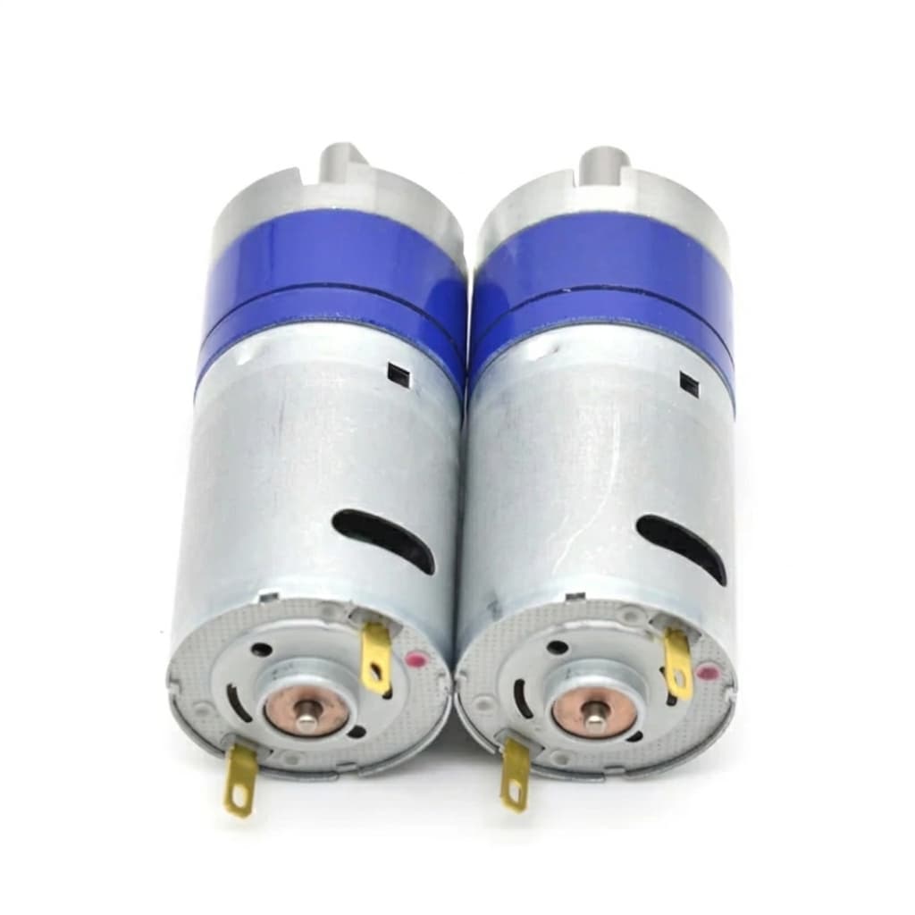
Micro BLDC Motor Sizing Guide for Compact Robotics
A practical engineering guide on calculating RMS torque, gear ratio efficiency, and thermal limits when specifying micro BLDC gear motors for robotic joints and grippers.
From highly dexterous surgical robots to automated warehouse grippers and quadrupeds, the dynamic performance of a robotic system is fundamentally bottlenecked by its actuators. Sizing a micro BLDC gear motor incorrectly can lead to sluggish movement, overheating joints, or premature gear failure.
For OEM engineers, shifting from a theoretical robotic model in CAD to specifying a physical motor for factory procurement requires converting kinematics into electrical and mechanical realities. Here is a practical, step-by-step guide to sizing micro BLDC motors for robotic applications.
Step 1: Calculate the Load Profile (RMS Torque)
The single most common mistake in motor sizing is selecting a motor based solely on the peak torque required by the joint. In robotics, a joint does not apply peak torque continuously; it accelerates, moves at a constant velocity, decelerates, and dwells (holds position).
To prevent thermal failure, you must calculate the Root Mean Square (RMS) Torque.
The RMS torque calculation integrates the different torque phases over the total cycle time (t_total):
Typical Robotic Joint Load Profile vs RMS Continuous Rating
T_RMS = sqrt((T_a^2 * t_a + T_c^2 * t_c + T_d^2 * t_d + T_h^2 * t_h) / t_total)Where:
- $T_a, t_a$ = Acceleration torque and time
- $T_c, t_c$ = Continuous running torque and time
- $T_d, t_d$ = Deceleration torque and time
- $T_h, t_h$ = Hold/Dwell torque and time
Rule of Thumb: The motor's Continuous Rated Torque (as listed on the factory datasheet) must be equal to or greater than your calculated T_RMS. If you simply match the continuous rating to your peak acceleration torque, you will significantly over-specify the motor, adding unnecessary weight and cost to the robot.
Step 2: Account for the Gearbox Constraints
Because micro BLDC motors naturally spin at high speeds (often 10,000 to 40,000 RPM) with low torque, robotic joints almost always require a reduction gearbox. Planetary gearboxes are the standard for compact, high-torque applications.
When sizing, you must account for Gearbox Efficiency ($\eta$): Motor Torque Required = (Target Joint Torque) / (Gear Ratio × $\eta$)
Design Trap: A 1-stage planetary gearbox might be 90% efficient, but a 3-stage or 4-stage gearbox required for high torque reduction (e.g., 256:1) may drop to 60-70% efficiency. Failing to account for this mechanical friction means your motor will stall before reaching the target payload.
Additionally, pay close attention to Backlash. Planetary gearboxes inherently have backlash (play between the gears), typically ranging from 1 to 3 degrees. If your robotic joint requires zero-backlash precision, you must specify a Harmonic Drive (strain wave gear), which is significantly more expensive.
Step 3: Speed and Voltage Margins
To move a robotic joint at a target velocity, the motor must spin at a corresponding RPM based on the gear ratio: Target Motor RPM = Joint RPM × Gear Ratio
However, you must leave a "voltage margin." Under heavy load, the motor's speed will naturally drop according to its speed-torque gradient. Also, the motor driver (ESC) rarely outputs 100% of the battery voltage due to PWM switching losses and battery voltage droop.
Best Practice: Select a motor winding with a No-Load RPM that is at least 20% to 30% higher than your absolutely required Target Motor RPM at your system's nominal voltage (e.g., 24V or 48V).
Step 4: The Importance of the Motor Constant ($K_m$)
When comparing two different micro BLDC motors of the exact same physical dimensions from different suppliers, evaluate the Motor Constant ($K_m$).
K_m is a measure of the motor's ability to produce torque relative to the resistive heat it generates, expressed in Nm/sqrt(W).
In confined robotic joints (like an elbow or ankle) where active air cooling is non-existent, thermal dissipation is the primary limiting factor. A motor with a higher $K_m$ will produce the required torque while generating less heat, allowing your robot to operate longer without triggering thermal shutdown limits.
Step 5: Positional Feedback (Encoders)
For a robotic joint to hold a precise position or execute a smooth trajectory via Field Oriented Control (FOC), the controller must know the rotor's exact electrical angle.
- Hall Effect Sensors: Standard on most micro BLDC motors. They provide basic commutation data (usually 6 steps per electrical revolution). This is sufficient for velocity control but completely inadequate for precision robotic positioning.
- Optical or Magnetic Encoders: For robotics, you must specify a high-resolution incremental or absolute encoder mounted to the rear of the motor. When multiplied by the gear reduction ratio, even a modest 512 CPR (Counts Per Revolution) encoder on the motor shaft translates to extremely high positional resolution at the joint output.
Sourcing Your Robotic Actuators
Sizing a motor mathematically is only the first step. The next critical phase is securing physical validation samples that match your calculated requirements exactly.
At Micro BLDC, we support robotics engineers by customizing stator windings to match specific voltage margins, integrating compact planetary gearheads, and installing high-resolution magnetic encoders directly at the factory level.
OEM RFQ Blueprint
Provide this snapshot in your inquiry for a rapid robotic joint motor calculation:
Joint Output RPM: [e.g., 30 RPM]
Peak Joint Torque ($T_a$): [e.g., 5 Nm]
RMS Joint Torque (`T_RMS`): [e.g., 1.5 Nm]
Max OD (Outer Diameter): [e.g., 36mm]
Backlash Tolerance: [e.g., < 1.5 degrees]
Feedback: [e.g., 512 CPR Magnetic Encoder]
Ready to transition from CAD to physical testing? Send us your RMS torque, speed, and dimensional limits, and our engineering team will propose a tailored micro BLDC motor and gearbox solution for your robot.
Author

Categories
More Posts
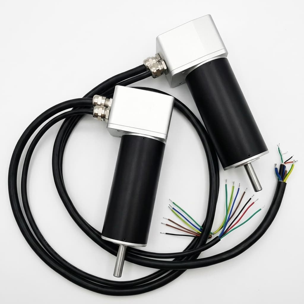
Coreless Brushless vs Traditional BLDC Motors: An Engineering Comparison
A deep-dive comparison between coreless (slotless) micro BLDC motors and slotted BLDC motors, covering inertia, PWM frequency requirements, cogging torque, and thermal time constants.
How to Select a Micro BLDC Motor for Medical Devices: An Engineering Deep Dive
Engineering notes on specifying low-noise, high-reliability micro brushless DC motors for surgical tools, pumps, and portable medical equipment, including EMI and thermal constraints.