
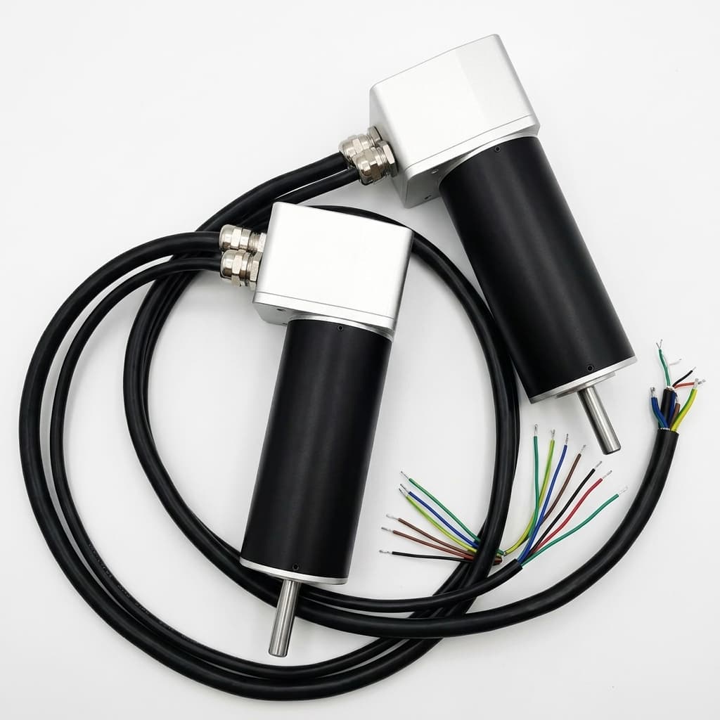
Coreless Brushless vs Traditional BLDC Motors: An Engineering Comparison
A deep-dive comparison between coreless (slotless) micro BLDC motors and slotted BLDC motors, covering inertia, PWM frequency requirements, cogging torque, and thermal time constants.
When designing compact robotics, high-speed optical scanners, drone gimbals, or precision hand tools, engineers face a critical architectural choice in actuator technology: Coreless (Slotless) Micro BLDC motors versus Traditional Slotted Micro BLDC motors.
While both are electronically commutated (brushless) and can support long service life when load, bearing stress, temperature, and duty cycle are validated, their internal magnetic architecture changes dynamic behavior, thermal limits, and driver requirements. This technical guide breaks down the engineering differences to help OEM procurement and design teams choose the better architecture for a defined operating profile.
1. Internal Architecture: Slotted vs. Slotless
Traditional Slotted BLDC Motors: In a slotted motor, the copper wire is wound around laminated iron teeth (stator slots). As the permanent magnet rotor spins, its magnetic poles are heavily attracted to these iron teeth. This magnetic interaction pulls the rotor toward the nearest iron tooth, creating a jerky, stepping sensation known as cogging torque.
Coreless (Slotless) BLDC Motors: In a coreless or slotless design, the copper windings are formed into a self-supporting basket or cylinder (often using rhombic or honeycomb winding techniques). This coil basket does not use slotted iron teeth. The rotor spins inside or outside this hollow copper cylinder. Because there are no stator teeth for the magnets to attract, cogging torque can be greatly reduced.
2. Performance Comparison Matrix
| Metric | Coreless (Slotless) BLDC | Traditional Slotted BLDC |
|---|---|---|
| Cogging Torque | Very low when winding geometry and rotor balance are controlled | Moderate to high without mitigation |
| Rotor Inertia | Low | Moderate to high |
| Acceleration / Dynamics | Application-specific; can be very fast with proper driver and current limits | Standard to fast, depending on rotor and control loop |
| Thermal Time Constant | Low (Susceptible to sudden overload) | High (Iron absorbs peak heat) |
| Low-Speed Smoothness | Good when driver resolution and commutation are matched | Can show cogging or ripple without advanced FOC |
| Cost | Higher (Complex winding process) | Lower (Automated mass production) |
3. Dynamic Response and Rotor Inertia
If your application requires rapid acceleration, such as pick-and-place machines, lidar spinning mirrors, or haptic feedback controllers, rotor inertia ($J$) becomes a primary selection variable. The mechanical time constant ($\tau_m$) helps describe how fast a motor responds to a voltage input.
- Coreless Motors usually have lower inertia because the winding structure and magnetic circuit reduce detent torque and rotating mass. A high-end coreless motor can deliver very fast start-stop response when the driver, current limit, load inertia, and thermal margin are designed together.
- Traditional BLDC Motors often have higher mechanical time constants. They can still reach high top speeds, but rapid start-stop-reverse profiles should be checked against rotor inertia, driver bandwidth, and heat rise.
4. The PWM Frequency Trap: Driver Requirements
A critical, often-overlooked engineering challenge when adopting Coreless BLDC motors involves the electronic speed controller (ESC) and its PWM (Pulse Width Modulation) frequency.
Because coreless motors lack an iron stator, their phase inductance ($L$) is extremely low (often in the microhenry $\mu H$ range).
If driven by a standard BLDC controller using a standard 20 kHz PWM frequency, the low inductance may not smooth out the current ripple. This can cause high-frequency current spikes (di/dt) and higher eddy-current and resistive heating losses.
Engineering Rule of Thumb: When driving a coreless micro BLDC motor, the controller usually needs a higher PWM switching frequency, often 60 kHz to 100 kHz, or additional external line chokes (inductors) to reduce current ripple and overheating risk.
5. Heat Dissipation and Overload Capacity (T_th)
This is where the traditional slotted motor holds a distinct advantage.
- Slotted Motors: The laminated iron stator acts as a large thermal heat sink. The thermal time constant (
T_th) of the winding is high. If the motor is suddenly stalled or overloaded, the iron core absorbs the excess heat from the copper windings, giving the controller a few seconds to detect the over-current and shut down before damage occurs. - Coreless Motors: Because the copper windings are suspended in air or potted in thin resin without an iron backing, their thermal time constant is very low (often just seconds). An accidental stall or large torque overload can overheat the copper windings quickly if current limiting and stall protection are not designed into the driver.
Summary: Which Should You Source?
Choose Coreless (Slotless) Micro BLDC if you need:
- Very low cogging and smooth rotation at low speed
- Fast acceleration and dynamic start-stop response
- Compact footprint and lightweight design for aerospace or medical hand tools
- High efficiency for battery-powered portable devices
Choose Traditional Slotted Micro BLDC if you need:
- Maximum peak torque and thermal robustness to survive mechanical shocks
- Cost-effective pricing for consumer or high-volume industrial products
- Continuous high-load operation (e.g., pumps, blowers, heavy-duty gear motors)
OEM RFQ Blueprint
When engaging a motor factory, provide these specs to get a precise quote on either architecture:
Application: [e.g., Gimbal Camera]
Target Speed: [e.g., 5000 RPM]
Acceleration Target: [e.g., 0 to 5000 RPM in 10ms]
Driver PWM Freq: [e.g., 60 kHz]
Max Diameter: [e.g., 16mm]
Not sure which architecture fits your product's performance profile, or need help matching a high-frequency driver to a coreless motor? Contact the Micro BLDC engineering team to review your mechanical and electrical constraints.
Author

Categories
More Posts
Micro BLDC Motor Sizing Guide for Compact Robotics
A practical engineering guide on calculating RMS torque, gear ratio efficiency, and thermal limits when specifying micro BLDC gear motors for robotic joints and grippers.
How to Select a Micro BLDC Motor for Medical Devices: An Engineering Deep Dive
Engineering notes on specifying low-noise, high-reliability micro brushless DC motors for surgical tools, pumps, and portable medical equipment, including EMI and thermal constraints.