Micro BLDC LogoMicro BLDC
Start inquiry
Micro BLDC LogoMicro BLDC
WhatsApp
Micro BLDC LogoMicro BLDC

Precision Micro BLDC Motor Engineering, Validation, and Manufacturing Support.

Inquiry Email

[email protected]

Email app

Include motor type, OD, voltage, speed, load, quantity, and destination.

Instant Chat

+86 18857971991

Chat on WhatsApp

Direct RFQ follow-up from our engineering team.

Products
  • Micro BLDC Motors
  • Micro Brushless DC Motors
  • Custom OEM Assemblies
  • Coreless Micro BLDC Motors
  • Low Noise Medical Micro BLDC
  • Long Life Micro BLDC Motors
  • High Speed Drone Micro BLDC
  • Hall & Encoder Micro BLDC
  • Micro BLDC Gear Motors
Solutions
  • Medical Devices
  • UAV and Drone
  • Compact Appliances
  • Robotics
  • Precision Instruments
OEM Capabilities
  • Custom Micro BLDC Engineering
  • Manufacturing Capabilities
  • Noise & Lifetime Validation
  • Quality & Inspection
  • Distributor & Sourcing Support
Resources
  • Blog
  • About
  • Contact / RFQ
  • Privacy Policy
  • Cookie Policy
  • Terms of Service
© 2026 Micro BLDC. All Rights Reserved.|Backed by Linkup Ai Co., Ltd. Manufacturing delivered by the Advanced Manufacturing Division of Linkup Precision.|Legal entity: Linkup Ai Co., Ltd.
← Back to Solutions

Precision Instruments Micro BLDC Motors

Low-vibration micro BLDC motors for optical equipment, laboratory devices, analyzers, and metrology instruments.
Target Buyer:For R&D teams building instruments where motor vibration or speed fluctuation ruins measurement accuracy.
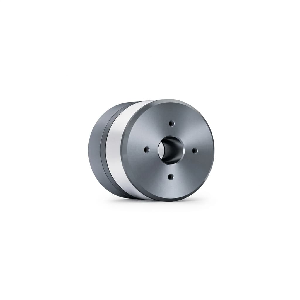
Precision Instrument Gimbal Motor

Solution Highlights

  • Vibration and speed ripple review for stable operation
  • Precision rotor balancing and premium bearing selection
  • Coreless and slotless options to reduce magnetic cogging

Common Use Cases

  • Optical scanners
  • Laboratory analyzers
  • Metrology devices
  • Laser steering

Implementation Focus

  • Reduce cogging torque through motor architecture selection
  • Balance rotor to agreed standards for lower vibration risk
  • Review EMI/RFI control needs to protect sensitive sensors

Application Decision Notes

Best-fit buyer

For R&D teams building instruments where motor vibration or speed fluctuation ruins measurement accuracy.

Validate Before Product Integration

  • Reduce cogging torque through motor architecture selection
  • Balance rotor to agreed standards for lower vibration risk

Application Inputs That Change Selection

  • Vibration and noise limits with mounting details
  • Speed stability requirements (wow and flutter)
  • Operating temperature and environmental cleanliness (e.g., cleanroom)

Application Validation and Production Flow

StageBuyer InputFactory / QC CheckpointDecision Output
RFQ feasibility reviewVibration and noise limits with mounting details; Speed stability requirements (wow and flutter)Reduce cogging torque through motor architecture selectionFeasibility notes, missing parameters, and sample direction.
Sample definition and validationOperating temperature and environmental cleanliness (e.g., cleanroom); Feedback resolution needed for precise speed controlSpeed ripple / Cogging: Low target defined by application and architectureControlled sample scope with measurable acceptance criteria.
Pilot lot and repeat productionPilot quantity, annual forecast, revision baseline, and destinationMechanical resonance amplifies motor vibration: Test the motor within the actual instrument chassis to identify and avoid resonant frequencies.Pilot records tied to emi sensitivity and outgoing inspection.

Application Evaluation Matrix

Evaluation MetricTypical RangeBuyer Relevance
Speed ripple / CoggingLow target defined by application and architecturePrevents optical distortion and maintains fluid dosing precision.
EMI sensitivityReviewed against sensor, PCB, cable, controller, and grounding layoutPrecision instruments can fail measurement repeatability when motor and controller noise couples into sensors.
Bearing and runoutBearing class, shaft runout, preload, and rotor balance defined by instrument toleranceMechanical runout and bearing vibration can be more damaging than nominal torque error.

RFQ Preparation Checklist

  1. Vibration and noise limits with mounting details
  2. Speed stability requirements (wow and flutter)
  3. Operating temperature and environmental cleanliness (e.g., cleanroom)
  4. Feedback resolution needed for precise speed control

Risk and Mitigation

  • Mechanical resonance amplifies motor vibration: Test the motor within the actual instrument chassis to identify and avoid resonant frequencies.
  • Motor vibration measured outside instrument chassis: Validate with the real mounting, load, controller, cable path, and sensitive sensor operating state.

Recommended Products

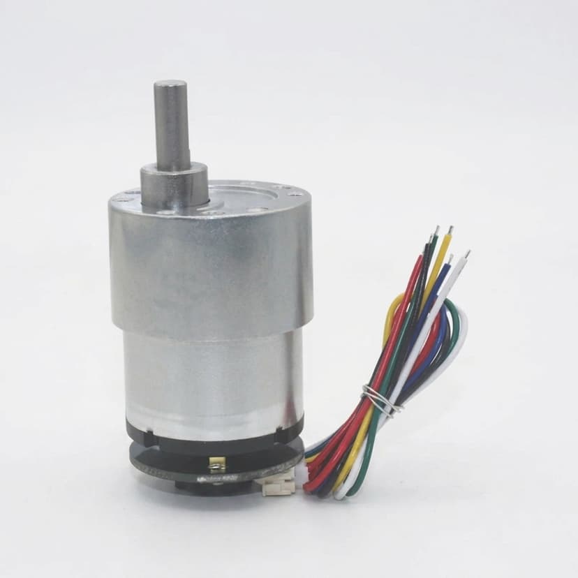
Precision Instrument Encoder Motor

Buyer FAQ

How do you validate low vibration for instruments?

We use bearing selection, dynamic rotor balancing, and can recommend slotless or coreless designs to reduce cogging under agreed test conditions.

When should precision instruments consider slotless or coreless motors?

Consider them when cogging, low-speed ripple, rotor inertia, or vibration affects measurement quality more than the lowest component cost.

Related Resources

  • Slotless Micro BLDC Motors
  • Coreless Micro BLDC Motors
  • Quality Inspection and Test Controls
  • Contact / RFQ

Inquiry Email

[email protected]

Email app

Include motor type, OD, voltage, speed, load, quantity, and destination.

Instant Chat

+86 18857971991

Chat on WhatsApp

Direct RFQ follow-up from our engineering team.